
Related Manuals for JEFF ROWLAND CORUS STEREO PREAMPLIFIER


Summary of Contents for JEFF ROWLAND CORUS STEREO PREAMPLIFIER
- Page 1 CORUS STEREO PREAMPLIFIER Operational Manual REV05 2010 © Jeff Rowland Design Group 2010 All Rights Reserved...
-
Page 2: Important Safety Instructions
must not be modified in any way, other than according CORUS PREAMPLIFIER to official service bulletins from JRDG (Jeff Rowland Design Group). Otherwise, the factory warranty will be immediately voided. Be sure the preamplifier is muted (volume level bracketed) before connecting or disconnecting any interconnect cables. - Page 3 NOTE FROM JEFF ROWLAND DESIGN GROUP elcome to the Jeff Rowland Design Group “family” and congratulations on your purchase of what is unquestionably one of the world’s finest preamplifiers. With its combination of features such as precision electronic circuitry, exceptional...
-
Page 4: Table Of Contents
TABLE OF CONTENTS Special Design Features ......................Maintenance and Care ......................Unpacking and Placement ...................... Initial Inspection ........................Unpacking ........................... Placement and Alignment ....................Front Panel ..........................Front Panel Display ......................Front Panel Controls ......................Menu Options ........................Rear Panel .......................... -
Page 5: Special Design Features
SPECIAL DESIGN FEATURES Preamplifier circuitry housed inside single ultra- MACHINED ALUMINUM CHASSIS: low resonance, structurally rigid chassis precision-machined from a solid ingot of aircraft grade 6061-T6 aluminum, completely sealed for trouble-free operation, yield maximum electrical/EMI/RF isolation. Power supply is confined inside external machined FUNCTIONAL ISOLATION: aluminum chassis. - Page 6 JRDG (Jeff Rowland Design Group) amplifiers a 140dB dynamic range interface can be achieved. All unbalanced inputs convert to balanced upon entering the preamp. 6 inputs (4 XLR balanced, 2 RCA unbalanced); 4 main FLEXIBLE CONNECTIVITY: outputs (2 XLR balanced, 2 RCA unbalanced); 2 record outputs (1 XLR balanced, 1 RCA unbalanced);...
- Page 7 the multi-function handheld remote transmitter. Rapid turns of the control knob adjust the volume by 1.5dB increments. Slow turns of the control allow for very fine adjustments by 0.5dB increments. No turn-on or turn-off transients during intermittent power QUIET POWER-UP: interruptions.
-
Page 8: Maintenance And Care
MAINTENANCE AND CARE All JRDG (Jeff Rowland Design Group) products are designed to provide a lifetime of enjoyment and listening pleasure. Chassis is sealed to prevent dust from entering the interior of the chassis and thus should never need interior cleaning during the lifetime of the product. All internal circuitry is maintenance-free such that no adjustments of any kind are necessary over the lifetime of the product. -
Page 9: Unpacking And Placement
We strongly suggest that you save all of the packing materials. If the preamplifier is returned to your dealer or JRDG (Jeff Rowland Design Group), the original packing materials must be used for shipment to avoid possible damage. Neither JRDG (Jeff Rowland Design Group) nor the shipper can be held responsible for damages incurred during transit if the original factory packing is not used. -
Page 10: Placement And Alignment
PLACEMENT AND ALIGNMENT Place the on a stable platform, rack, or shelf. The power supply CORUS PREAMPLIFIER can be placed up to two meters away from the preamplifier. All audio interconnects can be inserted into the rear panel at this time. Then each multi-pin DC cable can be inserted into the DC out receptacles. -
Page 11: Front Panel
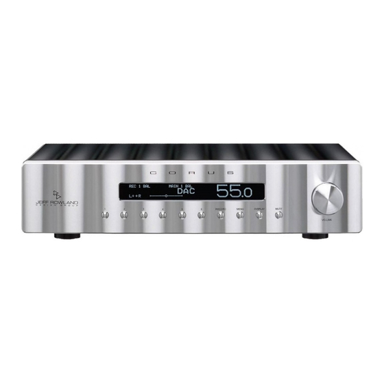
FRONT PANEL The front panel of the Corus Preamplifier’s chassis features a vacuum-fluorescent (VFD) display, 10 push-buttons, and a multi-purpose volume/menu control knob. All controls are precision machined from aluminum billet. Each pushbutton has been designed with a slightly different length to accommodate the curvature of the faceplate. FRONT PANEL DISPLAY Figure 2: Front Panel Display 1. - Page 12 5. CHANNEL BALANCE/OFFSET INDICATOR. The channel balance indicator is a horizontal bar graph located to the right of the phase indicator. The cursor changes from a small square to a diamond shape at the center of the bar graph when the left and right channels have identical gains, or when no input gain offset has been added to a selected input.
-
Page 13: Front Panel Controls
FRONT PANEL CONTROLS Figure 3: Front Panel Controls The main input number is selected by pressing the desired 1. INPUT BUTTONS 1-6. input button. mode 2. RECORD PUSHBUTTON. Enters the . The record input number is RECORD SELECT selected by pressing the front panel’s button and then pressing the desired input RECORD button. -
Page 14: Menu Options
MENU OPTIONS Several buttons enter and exit the : The front-panel’s button; the handheld MENU MENU remote transmitter buttons; and the front panel knob. From the ENTER EXIT VOLUME display’s main screen, pressing any of the buttons enters the mode. Once in MENU MENU mode, either the... - Page 15 OUT 2 OFFSET. Adjusts the input gain offset of the unbalanced (RCA) output OUT 2 relative to the balanced (XLR) by turning the knob MAIN OUTPUTS 1 VOLUME clockwise or counter-clockwise.The balance bar graph will indicate any degree of adjustment in 0.5dB increments when this mode is selected.
-
Page 16: Rear Panel
REAR PANEL Figure 4: Rear Panel 1. DC IN R/L POWER INPUT RECEPTACLES. Two separate DC power cables, one for each channel, are utilized to connect the power supply to CORUS PREAMPLIFIER 2. INPUTS. Four (4) pair Balanced (XLR), Two (2) pair Unbalanced (RCA) input jacks for each channel. -
Page 17: Handheld Remote Transmitter
HANDHELD REMOTE TRANSMITTER ’s infrared handheld remote CORUS PREAMPLIFIER transmitter is matched by a remote sensor unit that connects to the preamplifier via a 2 meter long cable. The hard wired connection allows the sensor unit to be placed up to 2 meters away from the preamplifier. NOTE: AN ACTIVITY LIGHT ON THE HANDHELD REMOTE TRANSMITTER ILLUMINATES DURING IR TRANSMISSION. -
Page 18: Remote Transmitter Controls
REMOTE TRANSMITTER CONTROLS Selects the Main Input number. If front panel BUTTONS 1 THROUGH 6. RECORD button is pressed, or the menu option is selected, the handheld RECORD SELECT remote buttons #1 through #6 will select the Record Input Number. Toggles between Phase Normal (L+ +R) and Invert Both (L−... -
Page 19: Remote Transmitter Battery Replacement
REMOTE TRANSMITTER BATTERY REPLACEMENT ’s handheld remote transmitter is powered by 2 standard CORUS PREAMPLIFIER alkaline double-A (AA) batteries. When the remote transmission range decreases or no longer operates, the batteries need to be replaced. Using a standard flat blade screw driver, unfasten the holding screw located in the bottom end of the transmitter unit. -
Page 20: General Operations
GENERAL OPERATIONS MUTE SETTINGS Pressing the button once on either the control panel or remote transmitter reduces MUTE the main volume by 20dB, and decreases the volume indicator by 20.0 counts. The display shows the volume indicator surrounded by corner brackets. Pressing button a second time mutes the main volume completely. -
Page 21: Adjusting Record Out Level
ADJUSTING RECORD OUT LEVEL Enter . Scroll and select . The main volume indicator shows the MENU RECORD OUT LEVEL gain of the selected input routed to the jacks. Adjust the level with the front RECORD-OUT panel’s volume knob or the remote’s buttons. -
Page 22: Specifications
SPECIFICATIONS Overall Gain Independently Programmable 0 to 20 dB on each input Gain Range 99.5 dB, 199 Equal Increments Gain Resolution 0.5 dB, +/- 0.03 dB Over Entire Range Frequency Response 10 Hz – 300 kHz, -3 dB @ 8 ohms Maximum Input Level 13.5 volts (RMS) @ 0 dB Gain Maximum Output Level...
Need help?
Do you have a question about the CORUS STEREO PREAMPLIFIER and is the answer not in the manual?
Questions and answers