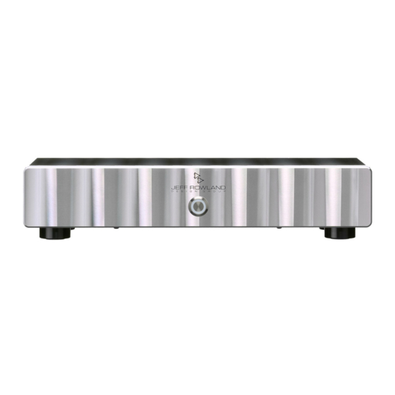
Summary of Contents for JEFF ROWLAND 125
- Page 1 MODEL 125 STEREO AMPLIFIER Operational Manual © Jeff Rowland Design Group 2014 All Rights Reserved...
-
Page 2: Important Safety Instructions
Please return the unit or contact the authorized dealer from whom you purchased this product for more information. REVA2 MODEL 125 STEREO AMPLIFIER PAGE 1... -
Page 3: Limited Warranty
THE ABOVE WARRANTY IS THE SOLE WARRANTY GIVEN BY JEFF ROWLAND DESIGN GROUP, INC. AND IS IN LIEU OF ALL OTHER WARRANTIES; ALL IMPLIED WARRANTIES OF... - Page 4 EXPIRATION OF THIS FIVE YEAR WARRANTY PERIOD, JEFF ROWLAND DESIGN GROUP, INC. SHALL HAVE NO FURTHER OBLIGATION OF ANY KIND WHETHER EXPRESSED OR IMPLIED. Jeff Rowland Design Group, Inc. does not authorize any third party, including any dealer or representative, to assume any liabilities on its behalf or to make any warranties on its behalf unless authorized to do so.
- Page 5 NOTE FROM JEFF ROWLAND DESIGN GROUP elcome to the Jeff Rowland Design Group “family” and congratulations on your purchase of what is unquestionably one of the world’s nest ampli ers. With its combination of features such as precision electronic circuitry, exceptional efficiency, and accurately machined chassis components throughout, your will offer you many...
-
Page 6: Table Of Contents
Unpacking and Placement ........................ Front Panel Operations ........................Rear Panel Connections ........................Connecting to Loudspeakers: Stereo Mode .................. Connecting to Loudspeakers: Bridge-Mode ................. Connecting to Loudspeakers: Bi-Amp Mode ................. Speci cations ........................... REVA2 MODEL 125 STEREO AMPLIFIER PAGE 5... -
Page 7: Special Design Features
"ring" or shut off the light altogether when the ampli er is powered on. A 1/8” (3.5mm) mini plug connector on rear panel permits ampli er REMOTE ON/OFF: power on/standby switching in remote and home theater applications. REVA2 MODEL 125 STEREO AMPLIFIER PAGE 6... -
Page 8: Maintenance And Care
The use of a cleanser or abrasive to clean the chassis that has not been approved by the factory will almost certainly damage the nish and will not be covered under warranty. REVA2 MODEL 125 STEREO AMPLIFIER PAGE 7... -
Page 9: Unpacking And Placement
1 Detachable IEC AC Power Cord Operational Manual Warranty Card IMPORTANT: RETAIN ALL PACKING MATERIALS FOR FUTURE TRANSPORT. SHIPPING PRODUCT IN INADEQUATE PACKING MATERIALS MAY VIOLATE THE JEFF ROWLAND DESIGN GROUP MANUFACTURER’S WARRANTY. REVA2 MODEL 125 STEREO AMPLIFIER... -
Page 10: Front Panel Operations
FRONT PANEL POWER BUTTON. Press this button to operate the ampli er. Press again to place the ampli er in Standby mode. POWER INDICATOR RING. This white ring will illuminate when the ampli er is operational. REVA2 MODEL 125 STEREO AMPLIFIER PAGE 9... -
Page 11: Rear Panel Connections
AC MAINS INPUT CONNECTOR. Install the AC Power Cable into the AC input connector between the ampli er and your AC mains outlet. REVA2 MODEL 125 STEREO AMPLIFIER PAGE 10... -
Page 12: Connecting To Loudspeakers: Stereo Mode
CONNECTING TO LOUDSPEAKERS: STEREO MODE Figure 3: Stereo Mode loudspeaker connections REVA2 MODEL 125 STEREO AMPLIFIER PAGE 11... -
Page 13: Connecting To Loudspeakers: Bridge-Mode
CONNECTING TO LOUDSPEAKERS: BRIDGE-MODE Figure 4: Bridge Mode loudspeaker connections REVA2 MODEL 125 STEREO AMPLIFIER PAGE 12... -
Page 14: Connecting To Loudspeakers: Bi-Amp Mode
CONNECTING TO LOUDSPEAKERS: BI-AMP MODE Figure 5: Bi-Amp Mode loudspeaker connections REVA2 MODEL 125 STEREO AMPLIFIER PAGE 13... -
Page 15: Specifications
SPECIFICATIONS Output Power 125 watts @ 8 ohms / 250 watts @ 4 ohms 500 watts @ 8 ohms BTL (bridge-tied load) Frequency Response 5 Hz – 130 kHz, -3 dB Dynamic Range 112 dBA (SE mode), 121 dBA (BTL mode) Output Noise 80 µV A - weighted...


Need help?
Do you have a question about the 125 and is the answer not in the manual?
Questions and answers