Table of Contents
Advertisement
Quick Links
CAT5 Multi VGA System
(VGA and Audio)
CUSTOMER
Order toll-free in the U.S.: Call 877-877-BBOX (outside U.S. call 724-746-5500)
SUPPORT
FREE technical support 24 hours a day, 7 days a week: Call 724-746-5500 or fax 724-746-0746
INFORMATION
Mailing address: Black Box Corporation, 1000 Park Drive, Lawrence, PA 15055-1018
Web site: www.blackbox.com • E-mail: info@blackbox.com
.
DECEMBER 2008
AC1000A-R3
AC1001A-R2
AC1002A-R3
AC1003A
AC1013A-R2
AC1014A-R2
AC1211A
Advertisement
Table of Contents

Subscribe to Our Youtube Channel
Related Manuals for Black Box AC1000A-R3


Summary of Contents for Black Box AC1000A-R3
- Page 1 Order toll-free in the U.S.: Call 877-877-BBOX (outside U.S. call 724-746-5500) SUPPORT FREE technical support 24 hours a day, 7 days a week: Call 724-746-5500 or fax 724-746-0746 INFORMATION Mailing address: Black Box Corporation, 1000 Park Drive, Lawrence, PA 15055-1018 Web site: www.blackbox.com • E-mail: info@blackbox.com...
- Page 2 CAT5 MULTI VGA SYSTEM...
-
Page 3: Federal Communications Commission
FCC/IC RFI STATEMENTS, EU DECLARATION OF CONFORMITY FEDERAL COMMUNICATIONS COMMISSION FEDERAL COMMUNICATIONS COMMISSION AND INDUSTRY CANADA RADIO FREQUENCY INTERFERENCE STATEMENTS This equipment generates, uses, and can radiate radio-frequency energy, and if not installed and used properly, INDUSTRY CANADA that is, in strict accordance with the manufacturer’s instructions, may cause interference to radio communication. RADIO FREQUENCY INTERFERENCE STATEMENTS It has been tested and found to comply with the limits for a Class A computing device in accordance with the specifications in Subpart B of Part 15 of FCC rules, which are designed to provide reasonable protection against... -
Page 4: Table Of Contents
3.2.2 AC1002A-R3, AC1013A-R2, AC1014A-R2........…12 3.2.3 Skew Compensation..……………...…........…13 3.3 Typical Applications..…........…........…...14 4. Troubleshooting....................15 4.1 Common Problems ...................15 4.2 Calling Black Box ..................16 4.3 Shipping and Packaging ................16 Appendix A. Cabling Pinouts................17 Appendix B. DC Restoration Setting ..............19 Appendix C. Receiver Video Settings..............20 Appendix D. -
Page 5: Specifications
SPECIFICATIONS 1.Specifications Cable Required: CatX (5/5e/6) UTP Compliance: CE; FCC Class A, IC Class/classe A Video Support: RGBHV, RGB, YUV, S-Video, composite, 75 ohm. Audio Support: 2 Channels Right/Left Summed (mono output) Resolution and (receiver dependent) Refresh Rate: AC1001A-R2 1366x768, 720P AC1002A-R3 1920x1080, 1080P;... - Page 6 CAT5 MULTI VGA SYSTEM Connectors: Transmitters: AC1000A-R3: (1) 4 captive screw, (1) RJ-45, (2) HD15 F; AC1003A: (2) 3.5-mm, (4) RJ-45, (2) HD15 F; Receivers: AC1001A-R2: (1) 3.5-mm, (1) RJ-45, (1) HD15 F; AC1002A-R3: (1) 4 captive screw, (2) RJ-45, (1) HD15 F;...
-
Page 7: Introduction
Category 5 cable. All models support RGBHV, RGB, and VGA video, and they use a transmitter-to-receiver setup. This manual covers the following CAT5 Multi VGA System Transmitters and Receivers: Transmitters: AC1000A-R3 Single port transmitter AC1003A 4 port Quad hub transmitter Receivers... -
Page 8: Package Contents
CAT5 MULTI VGA SYSTEM WARNING This equipment is not intended for, nor does it support, distribution through an Ethernet network. Do not connect these devices to any sort of networking or telecommunications equipment! 2.2 Package Contents You should have received the following when ordering a CAT5 Multi VGA System unit: •... -
Page 9: Setup And Installation
3. Make your audio connections. Connect the audio input to the AUDIO connector Pins 1 (Left Audio +) , 2 (ground), 3 (Right Audio +) for the AC1000A-R3 or the 3.5mm audio jack for the AC1003A. 4. Connect the CAT5 cable to the transmitter. -
Page 10: Transmitter Connections
CAT5 MULTI VGA SYSTEM 3.1.2 T RANSMITTER ONNECTIONS: Figure 3-1. Transmitter connections on the AC1000A-R3. Figure 3-2. Quad hub connections on the AC1003A. -
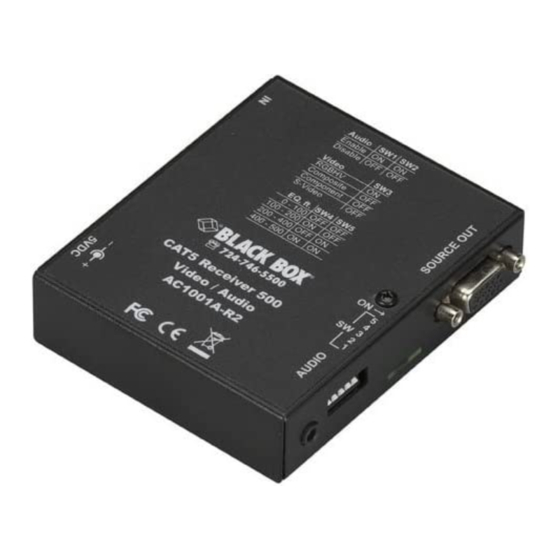
Page 11: Receiver Connections
CHAPTER 3: Setup and Installation 3.1.3 R ECEIVER ONNECTIONS: Figure 3-3. Receiver connections on the AC1001A-R2. Figure 3-4. Receiver connections on the AC1002A-R3. - Page 12 CAT5 MULTI VGA SYSTEM 3.1.3 R ECEIVER ONNECTIONS: Figure 3-5. Receiver connections on the AC1013A-R2. Figure 3-6. Receiver connections on the AC1014A-R2.
-
Page 13: Receiver Adjustments
CHAPTER 3: Setup and Installation 3.2 R ECEIVER DJUSTMENTS: This section details the tuning and adjustments for each receiver. The CAT5 Multi VGA system receivers have a single adjustment to compensate for different Cat5 cable lengths. This EQ process is easy and simple to do and must be done once unless the unit is moved to a different location. -
Page 14: Ac1002A-R3, Ac1013A-R2, Ac1014A-R2
The brightness in the white area should be the same as the white area above and below the black box. The Cable Length LEDs will turn on for indicated cable distances (AC1014A-R2). Starting from zero feet to 600/1200/2000 may take some time. -
Page 15: Skew Compensation
CHAPTER 3: Setup and Installation 3.2.3 Skew Compensation Settings The AC1211A, AC1013A-R2, AC1014A-R2 receivers are available with an optional skew compensation module to adjust for signal timing differences due to differing pair lengths within the CAT5 cable. Using the delay signals, skew may be compensated from 2 to 65 nanoseconds in 2 nanosecond increments on each individual color pair. -
Page 16: Typical Applications
CAT5 MULTI VGA SYSTEM 3.3 T YPICAL PPLICATIONS Figures 3-9 to 3-11 show typical applications: Figure 3-9. Point to Point Application Figure 3-10. 4 Display Distribution Figure 3-11. Daisy Chain Distribution... -
Page 17: Troubleshooting
CHAPTER 4: Troubleshooting 4. Troubleshooting 4.1. Common Problems In most cases, nearly every issue with the CAT5 Multi VGA System can be resolved by checking the CAT5 termination and making sure that it’s pinned to the TIA/EIA 568B wiring specification. However, there may be other problems that cause the system to not perform as it’s designed. -
Page 18: Calling Black Box
(see Appendix B). Quad hub transmitters (AC1003A) do not feature this, however the local monitor output of the AC1000A-R3 can be used to fix this. Problem: Notes on Daisy Chaining:... -
Page 19: Appendix A. Cabling Pinouts
APPENDIX A:Cabling Pinouts Appendix A. Cabling Pinouts Table A-1. HD15 video connector. RGBHV RGBS RGsB (VGA) Red + Red + Red + Green+ Green+ Green+ Blue+ Blue+ Blue+ — — — Red- Red- Red- Green- Green- Green- Blue- Blue- Blue- —... - Page 20 CAT5 MULTI VGA SYSTEM Appendix A. Cabling Pinouts Table A-2. AUDIO connector (AC1002A-R3, AC1013A-R2, AC1014A-R2, AC1000A-R3)) Audio Left Channel Pin 1 Ground Pin 2 Pin 3 Right Channel Pin 4 Table A-3. 1/8” (3.5 mm) Audio Connection (AC1003A) Channel 1...
-
Page 21: Appendix B. Dc Restoration Setting
The following diagrams show the switch location and settings for the AC1000A-R3 transmitter assembly. Note: Switch settings other than shown below may result in unpredictable performance and are not supported by Black Box. DC restore / AC coupling options: Disable:... -
Page 22: Appendix C. Receiver Video Settings
CAT5 MULTI VGA SYSTEM Appendix C. Receiver Video Modes The Cat5 Multi VGA System receivers feature the ability to display five component RGBHV computer video as well as RGBS, RGsB and full component RGB video. The transmitter units need no configuration changes. The AC1001A-R2 has an external switch (SW3) that controls whether RGBHV or non-RGBHV signals are in use. -
Page 23: Appendix D. Rackmounting Units
Below is a table showing the various rackmount kits available . Figure D-1 shows a typical rackmount application. Transmitters: Rackmount PN Description AC1000A-R3 AC1009 19” 1U high kit for 4 units horizontally. AC1010 19” 2U high kit for 2 rows of 4 units... -
Page 24: Appendix E. Daisy Chain Termination
CAT5 MULTI VGA SYSTEM Appendix E. Daisy Chain Termination The Cat5 Multi VGA System receiver units with a UTP output can be daisy chained along a single cat5. This applies to the AC1002A-R3, AC1013A-R2, and the AC1014A-R2. The AC1001A-R2 does not have this capability. When daisy chaining, it is important to ensure units have proper termination at the end, but no termination in the middle units. -
Page 25: Appendix F. Ddc Modes
Mode 3: Copy DDC information from a display into the AC1000A-R3 memory. In this mode, DDC information is first copied from a display into the AC1000A-R3 transmitter and stored in non-volatile RAM. Then the transmitter is connected to a video source and reports the copied DDC information to the video source when requested. -
Page 26: Appendix G. Sync Modes
CAT5 MULTI VGA SYSTEM Appendix G. Setting Sync Mode The AC1000A-R3 has the capability for fixed and agile sync. The default sync mode setting is for agile sync which replicates the source sync polarity signals. However some displays require a fixed sync polarity that is not possible to change at the video source. - Page 27 APPENDIX G: Sync Modes Appendix G. Setting Sync Mode The AC1002A-R3, AC1211A, AC1013A-R2, AC1014A-R2 have the capability for fixed and agile sync. The default sync mode setting is for agile sync which replicates the source sync polarity signals. However some displays require a fixed sync polarity that is not possible to change at the video source.
- Page 28 CAT5 MULTI VGA SYSTEM © Copyright 2008. Black Box Corporation. All rights reserved. 1000 Park Drive • Lawrence, PA 15055‐1018 • 724‐746‐5500 • Fax 724‐746‐0746 5320013-01 Rev 02...
Need help?
Do you have a question about the AC1000A-R3 and is the answer not in the manual?
Questions and answers