Table of Contents
Advertisement
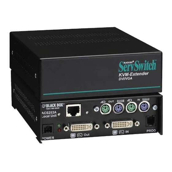
ServSwitch
Extend analog VGA or digital DVI video signals
over CAT5, CAT5e, or CAT6 UTP or multimode or
single-mode fiber cable.
Customer
Support
Information
ACS253A-CT
KVM Extender DVI/VGA
™
Order toll-free in the U.S.: Call 877-877-BBOX (outside U.S. call 724-746-5500)
FREE technical support 24 hours a day, 7 days a week: Call 724-746-5500 or fax 724-746-0746
Mailing address: Black Box Corporation, 1000 Park Drive, Lawrence, PA 15055-1018
Web site: www.blackbox.com • E-mail: info@blackbox.com
ACS253A-CT
ACS253A-MM
ACS253A-SM
BLACK BOX
Chapter
ACS253A-U-MM-R2
ACS253A-U-SM-R2
®
Advertisement
Table of Contents

Related Manuals for Black Box ServSwitch ACS253A-CT


Summary of Contents for Black Box ServSwitch ACS253A-CT
-
Page 1: Black Box
Order toll-free in the U.S.: Call 877-877-BBOX (outside U.S. call 724-746-5500) Customer FREE technical support 24 hours a day, 7 days a week: Call 724-746-5500 or fax 724-746-0746 Support Mailing address: Black Box Corporation, 1000 Park Drive, Lawrence, PA 15055-1018 Information Web site: www.blackbox.com • E-mail: info@blackbox.com ACS253A-CT... - Page 2 Trademarks Used in this Manual Trademarks Used in this Manual Black Box and the Double Diamond logo are registered trademarks of BB Technologies, Inc. Mac is a registered trademark of Apple Computer, Inc. Sun is a registered trademark of Oracle Corporation.
- Page 3 Interference Regulation of Industry Canada. Le présent appareil numérique n’émet pas de bruits radioélectriques dépassant les limites applicables aux appareils numériques de la classe A prescrites dans le Règlement sur le brouillage radioélectrique publié par Industrie Canada. Page 3 ACS253A-CT...
-
Page 4: Instrucciones De Seguridad
El aparato ha sido expuesto a la lluvia; o D: El aparato parece no operar normalmente o muestra un cambio en su desempeño; o El aparato ha sido tirado o su cubierta ha sido dañada. 724-746-5500 | blackbox.com Page 4 ACS253A-CT... - Page 5 Optical ports must be terminated with an optical connector or with a dust plug. Failure to adhere to the above restrictions could result in a modification that is considered an act of “manufacturing” and will require, under law, recertification of the modified product with the U.S. Food and Drug Administration (ref. 21 CFR 1040.10(i)). Page 5 ACS253A-CT...
-
Page 6: Table Of Contents
Front Panel, All Models (ACS253A-CT, ACS253A-MM, ACS253A-SM, ACS253A-U-MM-R2, ACS253A-U-SM-R2) .. 13 2.6.2 ServSwitch KVM Extender DVI/VGA, PS/2 Dual Access, CATx (ACS253A-CT) Remote and Local Unit Back Panels .. 14 2.6.3 ServSwitch KVM Extender DVI/VGA, PS/2 Dual Access, Fiber (ACS253A-MM and ACS253A-SM) ) Remote and Local Unit Back Panels ............................ -
Page 7: Quick Setup
4. Power up the system. Carry out the Monitor Setup procedure (see its manual and Chapter 5 in this manual). Carry out the VGA Input Setup procedure (see Section 6.2 in this manual). Figure QS-1. Quick Setup Instructions Page 7 ACS253A-CT... -
Page 8: Qs1. Video Input/Output
Table QS-2. Local Video Output Video Quality Local Unit Input Remote Unit Output QS3. Command Summary The following table summarizes the hotkey command sequences used in system configuration and video tuning on a remote unit console. 724-746-5500 | blackbox.com Page 8 ACS253A-CT... - Page 9 <Enter> <S> Select parameter modification < Enter > <S> Increase parameter <Right Arrow> <R> Decrease parameter <Left Arrow> <L> Accept and store modified parameter <Enter> <S> Back to the menu selection * Commands are not case sensitive. Page 9 ACS253A-CT...
-
Page 10: Specifications
Digital: DVI Distance (Maximum) — ACS253A-CT: 328.1 ft. (100 m) over CAT5, CAT5e, or CAT6 cable; ACS253A-MM, ACS253A-U-MM-R2: 656.1 ft. (200 m) using 62.5-/125-µm cable, 1312.3 ft. (400 m) with 50-/125-µm cable; ACS253A-SM, AC253A-U-SM-R2: 6.2 mi. (10 km) using 9-/125-µm cable Resolution (Maximum) —... -
Page 11: Overview
• All control and video tuning carried out using an on screen display (OSD) with settings stored in EEPROM memory. • Local/remote unit firmware and settings are flash upgradable. • Intelligent PS/2 keyboard and mouse emulation ensures PCs do not lock up and enables peripherals to be hot-plugged. Page 11 ACS253A-CT... -
Page 12: Available Models
There are five products in the range and various upgrade kits: PS2 Style Kits: • ACS253A-CT DVI Extender Set: PS2 Dual Access, CATx • ACS253A-MM DVI Extender Set: PS2 Dual Access, Multimode • ACS253A-SM DVI Extender Set: PS2 Dual Access, Single-mode USB Style Kits: •... -
Page 13: Hardware Description
(see Appendix E). • (1) U.S.-type power cord (additional) If anything is missing or damaged, contact Black Box Technical Support at 724-746-5500 or info@blackbox.com. 2.6 Hardware Description Figures 2-1 through 2-6 illustrate the front and back panels of the ServSwitch KVM Extenders. Tables 2-1 through 2-6 describe their components. -
Page 14: Servswitch Kvm Extender Dvi/Vga, Ps/2 Dual Access, Catx (Acs253A-Ct) Remote And Local Unit Back Panels
Chapter 2: Overview 2.6.2 ServSwitch KVM Extender DVI/VGA, PS/2 Dual Access, CATx (ACS253A-CT) Remote and Local Unit Back Panels ASC253A-CT Remote Unit Back Panel Figure 2-1. ACS253A-CT remote unit back panel. Table 2-1. ACS253A-CT remote unit components. Number Component Description... - Page 15 Chapter 2: Overview ASC253A-CT Local Unit Back Panel Figure 2-2. ACS253A-CT local unit back panel. Table 2-2. ACS253A-CT local unit components. Number Component Description Video Signal LED* (green) On when attached and valid mode detected; off when not attached and detected...
-
Page 16: Servswitch Kvm Extender Dvi/Vga, Ps/2 Dual Access, Fiber (Acs253A-Mm And Acs253A-Sm) Remote And Local Unit Back Panels
Lights on when device is ready; off when device is not ready 4-pin power connector Links to 6-V power supply *NOTE: For more details about the LED indicators, see Table 3-1 in Section 3.3. 724-746-5500 | blackbox.com Page 16 ACS253A-CT... - Page 17 DVI-I connector Out Connects to local conosle monitor DVI-I connector In Connects to CPU video card output RJ-22 connector Programming connector for firmware upgrades *NOTE: For more details about the LED indicators, see Table 3-2 in Section 3.3. Page 17 ACS253A-CT...
-
Page 18: Servswitch Kvm Extender Dvi/Vga, Usb Dual Access, Fiber (Acs253A-U-Mm-R2 And Acs253A-U-Sm-R2) Remote And Local Unit Back Panels
Lights on when device is ready; off when device is not ready 4-pin power connector Links to 6-V power supply *NOTE: For more details about the LED indicators, see Table 3-1 in Section 3.3. 724-746-5500 | blackbox.com Page 18 ACS253A-CT... - Page 19 DVI-I connector Out Connects to local console monitor DVI-I connector In Connects to CPU video card output RJ-22 connector Programming connector for firmware upgrades *NOTE: For more details about the LED indicators, see Table 3-2 in Section 3.3. Page 19 ACS253A-CT...
-
Page 20: Compatibility
Fiber—see Appendix D: Video Modes and Frame Rates). 2.8 Typical Application Local Access Local unit KVM extension over CATx or fiber optic cables Remote unit USB extension options (USB models only) Figure 2-7. KVM extender system 724-746-5500 | blackbox.com Page 20 ACS253A-CT... -
Page 21: How To Use This Guide
Interconnection Cable For ACS253A-CT Extenders, you will need CATx (any Category 5, 5e, 6, or higher) cable, terminated with RJ-45 plugs, to connect the local and remote units. Other units require single-mode or multimode fibers (see Section 3.1, Interconnection Cable Requirements). -
Page 22: Installation
KVM switches, this may not work. Contact Black Box Technical Support at 724-746-5500 or info@blackbox.com to discuss your application. 3. C onnect the interconnect cable to the interconnect socket(s) (Component #13 in Chapter 2: Figure 2-2 [ACS253A-CT], Figure 2-4 [ACS253A-SM/MM], or Figure 2-6 [ACS253A-U-SM-R2/MM-R2]). -
Page 23: Diagnostic Leds
LEDs are to the left and right, respectively, of the Interconnect sockets. The Device Ready and Video Signal LEDs are next to the Power socket. As an example, the location of the LEDs is shown in Figure 3-1 and Tables 3-1 and 3-2 for ACS253A-CT Remote and Local units: See also Chapter 2: Figures 2-1 through 2-6. -
Page 24: Access Switching
Table 3-2. ACS253A local unit LEDs. Number Component Appearance Description No communication errors for more than 60 minutes Indicates number of communication errors during previous 60 minutes. For ACS253A-CT: For ACS253A-xM and ACS253-U-xM-R2: Slow: 10-100 (CATx) 1-2 (Fiber) Communication Error LED Flashing Medium: 100-1000 (CATx) -
Page 25: Device Control
• Use the left and right arrow keys to highlight a submenu and/or function. • Press the <ENTER> key to select the highlighted submenu or function. • Select the Exit icon to go back to the previous menu level. Page 25 ACS253A-CT... - Page 26 • Use the <L> and <R> keys to highlight a submenu and/or function. • Press the <S> key to select the highlighted submenu or function. • Select the Exit button to go back to the previous menu level. 724-746-5500 | blackbox.com Page 26 ACS253A-CT...
-
Page 27: Using The Osd
(Contrast, for example), the OSD displays a value bar: Figure 4-2. OSD value bar. 5. Use the Left and Right arrow keys (<L> and <R> keys in Windows program) to change the value as required. Page 27 ACS253A-CT... - Page 28 Use the Input Select menu to specify the type of video signal to be used by the local unit. The actual graphics source is displayed with a “√ symbol (for example, VGA√). 724-746-5500 | blackbox.com Page 28 ACS253A-CT...
- Page 29 800 x 600, 1024 x 768, or 1280 x 1024. Figure 4-5. Scale Mode menu. Downscaling is only available with VGA signals. With a DVI input, you can select downscaling but it will not work—only upscaling has an effect. Page 29 ACS253A-CT...
- Page 30 View Color temperature submenu (see Color Temperature on the next page) Flesh tone/skin tone Set up colors in CMY space— automatically adjusts settings in RGB space Hue Saturation Back to main menu Figure 4-7. Color menu. 724-746-5500 | blackbox.com Page 30 ACS253A-CT...
- Page 31 Manually adjust the vertical screen position Manually adjust the horizontal screen position Manually adjust the Manually adjust the best phase number of pixels per line (best point for analog/digital (Pixel clock) conversion within each pixel) Figure 4-9. Image menu. Page 31 ACS253A-CT...
- Page 32 OSD window Back to Tools menu Manually adjust the vertical position of the OSD window Toggle the size of the OSD window between single and double size Figure 4-11. OSD submenu. 724-746-5500 | blackbox.com Page 32 ACS253A-CT...
- Page 33 32768 colors 262144 colors 7 bits/color 8 bits/color High 21 bits total 24 bits total 2.1M colors 16.78M colors To view this menu, select the Tools icon from the main menu and then select the Color Depth icon. Page 33 ACS253A-CT...
- Page 34 Chapter 4: Device Control Select low color mode/ higher fps Select high color mode/ lower fps Back to Tools menu Figure 4-13. Color Depth submenu. 724-746-5500 | blackbox.com Page 34 ACS253A-CT...
-
Page 35: Monitor Setup
7. If the picture quality is not acceptable after the automatic adjustment, you will have to manually adjust the pixel clock and pixel phase (in this order). Follow the instructions in your monitor’s user manual. 8. Press any key to exit the test pattern display. 9. Exit the OSD. Page 35 ACS253A-CT... -
Page 36: Extender Setup
Display | Backgrounds. Search for the downloaded burst file, using “Search for.” Select the tiled display option. Your desktop should show fine black-and-white vertical stripes over the entire desktop. 3. Display the OSD (see Chapter 4). 724-746-5500 | blackbox.com Page 36 ACS253A-CT... - Page 37 10. If appropriate, reattach your TFT monitor and adjust its image according to the manufacturer’s instructions. 11. Reinstall your preferred desktop background picture. Figure 6-1. Burst test pattern applied to desktop showing problems with (a) pixel clock setting, (b) pixel phase setting. Page 37 ACS253A-CT...
-
Page 38: Troubleshooting
Possible Cause/Solution: The pixel clock and/or phase is misaligned: Refer to Section 6.2. Problem: Characters are smeared. Possible Cause/Solution: The phase is misaligned: Refer to Section 6.2. Problem: Thin vertical lines are missing. Possible Cause/Solution: The phase is misaligned: Refer to Section 6.2. 724-746-5500 | blackbox.com Page 38 ACS253A-CT... -
Page 39: Keyboard And Mouse
If you determine that your ServSwitch KVM Extender DVI/VGA is malfunctioning, do not attempt to alter or repair the unit. It contains no user-serviceable parts. Contact Black Box Technical Support at 724-746-5500 or info@blackbox.com. Before you do, make a record of the history of the problem. We will be able to provide more efficient and accurate assistance if you have a complete description, including: •... -
Page 40: Appendix A. Example Applications
• CATx with audio/serial support (Figure A-2). • Multiple-head application with PS/2 keyboard/mouse, USB support, and audio/serial in 19”/1U (Figure A-3). For more details, please discuss suitable extension architecture with Technical Support (see Section 7.3, Contacting Black Box). Local console... - Page 41 Appendix A: Example Applications CPU, PS/2 keyboard and mouse, graphics and audio/ serial output Local console ACS253A-CT Local unit ACS253A-CT Remote unit Remote console Figure A-2. CATx application with local access. (3) CPUs DVI-I USB ACS253A-U-MM-R2 Local unit and RMK253A...
-
Page 42: Appendix B. Rackmount Options
3. Close the remaining gaps with blanking plates. The kit enables you to mount various combinations of regular and double-width housings: Figure B-2. One regular unit. Figure B-3. Two regular units. (using two small plates). (using one small plate). 724-746-5500 | blackbox.com Page 42 ACS253A-CT... - Page 43 Appendix B: Rackmount Options Figure B-4. Three regular units. Figure B-5. One double-width unit (using wide plate). Figure B-6. Double-width and regular unit (using narrow strip). Page 43 ACS253A-CT...
-
Page 44: Appendix C. System Upgrade And Dual Access
You might need to update the system firmware. Normally, this procedure is carried out in the factory. If you want to update the firmware yourself, contact Black Box Technical Support at 724-746-5500 or info@blackbox.com. You will need a programming cable and software to carry out the update. Follow the supplied instructions carefully. -
Page 45: Appendix D. Video Modes And Frame Rates
49.7 VESA guidelines 1024 48.3 VESA standard 1024 56.4 mode 1024 57.8 ® VESA standard 1024 68.6 DMTI 185 1152 63.8 VESA standard 1152 63.8 DMT1 185 1152 67.5 mode 1152 61.8 ® VESA standard 1280 60.0 Page 45 ACS253A-CT... - Page 46 To gain a higher frame rate, reduce the screen resolution—video normally does not require higher resolutions. NOTE: In higher resolution, the mouse pointer may show broken movement over the screen because of the reduced frame rate. Use slower mouse movements for exact positioning. 724-746-5500 | blackbox.com Page 46 ACS253A-CT...
-
Page 47: Appendix E. Usb-High Power/Low Power
Using the power supply unit, you may attach: • 1 to 4 high power units or • 1 to 4 low power units or • Any combination of these Each port has a regulated power limit of 500 mA. Page 47 ACS253A-CT... -
Page 48: Appendix F. Audio/Serial Upgrade
VGA/DVI video. To set up the extender’s audio and serial link, please follow all the instructions detailed in this appendix. If you have any questions, contact Black Box Technical Support at 724-746-5500 or info@blackbox.com. Serial Interface—Setup and Operation No setting up or user adjustments are required. -
Page 49: Appendix G: Connectors And Cables
Not connected DDC input (SCL) +5 V power TMDS clock GND DDC output (SDA) TMDS clock + Analog VSYNC Hot plug recognition TMDS clock - Analog red — — Analog blue Analog green Analog GND Analog HYSNC Page 49 ACS253A-CT... - Page 50 Mouse clock Not connected Keyboard In/Out Figure G-3. 6-pin mini DIN female keyboard connector. Table G-3. 6-pin mini DIN female keyboard connector pinning. Signal Keyboard data Not connected +5 V Keyboard clock Not connected 724-746-5500 | blackbox.com Page 50 ACS253A-CT...
- Page 51 Table G-4. RJ-22 programming connector pinning. Signal TxD (to PC RxD) RxD (from PC TxD) DTR from PC Power Figure G-5. 4-pin power connector. Table G-5. 4-pin power connector pinning. Signal Earth Not connected +6 VDC Housing Shield Page 51 ACS253A-CT...
-
Page 52: Adapter Cables
Remote/Local Unit: DVI-I male connector Figure G-6. DVI-I male connector. Table G-6. DVI-I male connector pinning. Signal DDC input (SCL) DDC output (SDA) Analog VSYNC Analog red Analog green Analog blue Analog HYSNC Analog GND 724-746-5500 | blackbox.com Page 52 ACS253A-CT... - Page 53 Monitor: HD15 female connector Figure G-7. HD15 female connector. Table G-7. HD15 female connector pinning. Signal DDC input (SCL) DDC output (SDA) Analog VSYNC Analog red Analog green Analog blue Analog HYSNC 6, 7, 8 Analog GND Page 53 ACS253A-CT...
- Page 54 CPU graphics card: HD15 male connector Figure G-8. HD15 male connector. Table G-8. HD15 male connector pinning. Signal DDC input (SCL) DDC output (SDA) Analog VSYNC Analog red Analog green Analog blue Analog HYSNC 6, 7, 8 Analog GND 724-746-5500 | blackbox.com Page 54 ACS253A-CT...
- Page 55 Appendix G: Connectors and Cables Figure G-9. DVI-I male connector. Table G-9. HD15 male connector pinning. Signal DDC input (SCL) DDC output (SDA) Analog VSYNC Analog red Analog green Analog blue Analog HYSNC 6, 7, 8 Analog GND Page 55 ACS253A-CT...
- Page 56 About Black Box Black Box provides an extensive range of networking and infrastructure products. You’ll find everything from cabinets and racks and power and surge protection products to media converters and Ethernet switches all supported by free, live 24/7 Tech support available in 30 seconds or less.
Need help?
Do you have a question about the ServSwitch ACS253A-CT and is the answer not in the manual?
Questions and answers