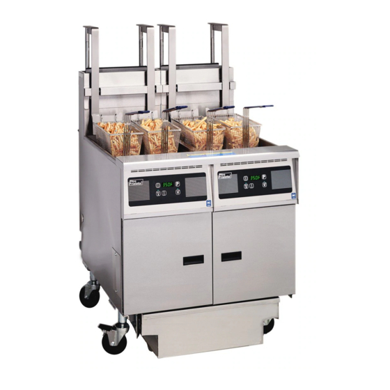
Pitco SGH50 Full Technical Service Information
Technical service and exploded parts covering models full and twin
Hide thumbs
Also See for SGH50 Full:
- Specifications (2 pages) ,
- Installation and operation manual (36 pages) ,
- Pm instructions (4 pages)
Table of Contents
Advertisement
Advertisement
Table of Contents
Troubleshooting

Related Manuals for Pitco SGH50 Full


Summary of Contents for Pitco SGH50 Full
- Page 1 Covering Models SGH50 Full and Twin P.O. Box 501, Jct I-89 & I-93 Concord, NH 03302-0501 • 509 Route 3A, Bow, NH 03304 Pitco Frialator, Inc., (800) 258-3708 • (603) 225-6684 • FAX (603) 225-8497 www.pitco.com L22-235 Rev 1 (10/12)
- Page 2 WARNING! FIRE HAZARD THE OIL LEVEL SHOULD NOT FALL BELOW THE MINIMUM INDICATED LEVEL AT ANY TIME. THE USE OF OLD OIL CAN BE DAGEROUS AS IT WILL HAVE A REDUCED FLASH-POINT AND BE MORE PRONE TO SURGE BOILING. WARNING INSTALLATION AND ALL CONNECTIONS MUST BE MADE ACCORDING TO NATIONAL AND LOCAL REGULATIONS AND CODES IN FORCE.
-
Page 3: Table Of Contents
Table of Contents How Does It Work? ............4 Component Troubleshooting..........4 Temperature Probe Resistance Chart ......... 5 Basic Trouble Shooting ............8 Relay Board Component Explanation ........ 10 Ladder Diagram ..............13 Schematics ................. 14-19 Basic Parts List..............21 Exploded Drawings ............ -
Page 4: How Does It Work
Chapter 1: HOW DOES IT WORK? Filter System: The SGH50 fryer components function in specific order • Opening the RED return valve handle will close of operation. Knowing and understanding the sequence the proximity switch causing the "pump run" relay of fryer and components operation will enable you to to be energized. - Page 5 This test will cause the burners to run continuously. Remove test resistor when test is complete. Leaving the test resistor in the fryer could cause damage to equipment and/or personal injury. To test the hi-limit, use a 2kΩ - 5kΩ resistor to simulate a 230°F - 275°F temperature.
- Page 6 indicator will be illuminated if the F1 fuse is good and the output at pin #9 (side on). board is receiving 24 VAC. •When the controller calls for heat, there will be a 24 VDC output at pin #8 (heat demand) and a 24 VAC input at pin Ignition Module: #6 (heat feed back).
- Page 7 controller has been unplugged, the primary controller will controller for continuity. not work. The jumper must be installed on the relay board •If display reads "Prob" "HI", ohm test the temperature (connection J33) to allow the primary controller to func- probe and the wires and connectors between the probe tion if the backup controller is removed.
- Page 8 Fryer Trouble Shooting PROBLEM POSSIBLE CAUSE ACTION Controller will NOT turn ON A. No power to the machine A. Check building circuit breaker, verify Display does NOT light B. F1 Fuse blown power cord is plugged in C. T1 Transformer B.
- Page 9 Filter Trouble Shooting PROBLEM POSSIBLE CAUSE ACTION Red return handle is pulled out, but no A. Red return handle not completly A. Pull on red return handle to make sure pump sound can be heard open valve is completly open B.
-
Page 10: Relay Board Component Explanation
Note: J connectors are marked on the relay board. •With 24 VAC supplied to pin #2 at PITCO# 60127301A connector J35 and a good F1 fuse, the DATE: MMDDYY relay board will have a 24 VAC output at pin #2 on connectors J33 and J34 H.D. - Page 11 L22-235 Rev 1 (10/12)
-
Page 12: Schematics
Schematics L22-235 Rev 1 (10/12) - Page 13 F1 FUSE L22-235 Rev 1 (10/12)
- Page 14 L22-235 Rev 1 (10/12)
- Page 15 L22-235 Rev 1 (10/12)
- Page 16 LOCATION SHEET 4, E4, J4 SHEET 4, J6 SHEET 4, C3 SHEET 4, H3 SHEET 4, C3 SHEET 4, G3 SHEET 4, C4 SHEET 4, H4 SHEET 4, G2 SHEET 4, G2 L22-235 Rev 1 (10/12)
- Page 17 L22-235 Rev 1 (10/12)
- Page 18 LOCATION SHEET 2, B3 B2004201-C SHEET 2, J3 SHEET 2, J3 SHEET 2, J3 SHEET 2, C6 SHEET 2, C6 SHEET 2, B3 B2004202-C SHEET 2, E6 SHEET 2, F2 B6700604-C SHEET 2, G7, C1 SHEET 2, I4 B5305001 SHEET 2, I4 SHEET 2, B6 SHEET 2, B6 SHEET 2, E3...
- Page 19 L22-235 Rev 1 (10/12)
-
Page 20: Exploded Drawings
Exploded Drawings and Parts Lists L22-235 Rev 1 (10/12) - Page 21 Parts Listing Fryer Components: 60133501 ....120V Heat Tape (Flush Hose) 60133502 ....230/240V Heat Tape (Flush Hose) Part Number ..Description PP11104 ....1” Viton O-ring 60138701 ....Full/LH Non Locking Drain Valve PP10084 ....Hi Limit Switch 60138702 ....RH Non Locking Drain Valve PP10429 ....
- Page 22 Table 1 Element and Tank Components Item# Part# Part Description 1..... A1103204 ......Basket Hanger 2..... A4107802 ......Splash Back 3..... 60138101 ......Basket Hanger Stud 60118201 ......Bolt,Hex 1/4-20 X 3/4 4..... PP10084........ Hi Limit Switch 5..... PP11366 ........ Screw, 10-24 X 5/8 PHH SS TF 6.....
- Page 23 Figure 1 L22-235 Rev 1 (10/12)
-
Page 24: Pump Box And Drain Manifold
Table 2 Check & replace if defective Pump Box and Drain Manifold Item# Part# Part Description 1..... 60130301 ......120/24V Transformer 60130302 ......230-240/24VAC Transformer 60130303 ......208VAC Transformer 2..... 60077901 ......10A Circuit Breaker (120V) 60078502 ......5A Circuit Breaker (208V-240V) 3..... - Page 25 Pump Entrance Box (viewed from bottom) Figure 2 L22-235 Rev 1 (10/12)
- Page 26 Table 3 Main Entrance Box Item# Part# Part Description 1 ..... 60130701 ......IEC In & Out Connector 2..... PP10689........ Screw, 6-32 X 1/2 3 ..... A2958102 ......Switch Cover 120V A2958104 ......Switch Cover 208V A2958106 ......Switch Cover 220V/240V 4 .....
- Page 27 Figure 3 L22-235 Rev 01(10/12)
-
Page 28: Pump Assembly And Filter Pan
Table 4 Pump Assembly and Filter Pan Item# Part# Part Description 1 ......B4004501 ........Full Return Handle B4004601 ........Left Split Return Handle B4004701 ........Right Split Return Handle 2 ......P0190200 ........Cotter Pin 1/16”x3/4” 3 ......60131901........Washer, Spring 5/8” with 5/16” Hole 4 ...... - Page 29 Figure 4 L22-235 Rev 1 (10/12)
- Page 30 B6747001 WRG,RELAY BRD NO BKUP OPT B6746501 HARNESS, RELAY BOARD TO COMPUTER OR DIGITAL CONTROLLER B6744601 HARNESS, RH MODULE B6744602 HARNESS, LH MODULE B6744603 HARNESS, RH CE MODULE B6744604 HARNESS, LH CE MODULE B6746601 HARNESS, RELAY BOARD TO SOLID STATE CONTROLLER 3.25 13.00 B6745502 HARNESS, HI LIMIT...
- Page 31 SCHEMATIC 60.00 1.25 1.25 B6749301 CABLE, INTERNAL REMOTE 1.25 4.50 228.00 SCHEMATIC TO REAR TO HOOD MOUNTED OF FRYER CONTROLLER B6749401 CABLE, EXTERNAL REMOTE 60128403 CORD,M-F JUMPER IEC-320X34” 60133901 CORD,MALE IEC-320 16-3 AWG 60133902 CORD,16-3 W/IEC320 MALE 66" 60128501 CORD, FEMALE IEC/NEMA 5-15 Figure 6 L22-235 Rev 1 (10/12)
- Page 32 Pitco Frialator factory, your order, please contact the Pitco Frialator Autho- from 8:00 a.m. - 5:00 p.m., Eastern Standard Time,...
Need help?
Do you have a question about the SGH50 Full and is the answer not in the manual?
Questions and answers