Jet GH-1440ZX Operation And Maintenance Instructions
Zx-series large bore lathes
Hide thumbs
Also See for GH-1440ZX:
- Operating instructions manual (84 pages) ,
- Brochure (56 pages) ,
- Specifications (20 pages)
Table of Contents
Advertisement
Quick Links
Operation and Maintenance Instructions
ZX-Series Large Bore Lathes
Models GH-1440ZX
GH-1640ZX/1660ZX
GH-1860ZX/1880ZX
GH-2280ZX
* For ZX-Series Lathes Parts List & Electrical Diagrams, see document M-321910-1
JET
427 New Sanford Road
LaVergne, TN 37086
Ph.: 800-274-6848
www.jettools.com
1
This .pdf document is bookmarked
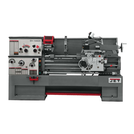
Model GH-1440ZX shown
Part No. M-321910
Revision J2 08/2018
Copyright © 2017 JET
Advertisement
Chapters
Table of Contents

Related Manuals for Jet GH-1440ZX


Summary of Contents for Jet GH-1440ZX
- Page 1 Operation and Maintenance Instructions ZX-Series Large Bore Lathes Models GH-1440ZX GH-1640ZX/1660ZX GH-1860ZX/1880ZX GH-2280ZX Model GH-1440ZX shown * For ZX-Series Lathes Parts List & Electrical Diagrams, see document M-321910-1 427 New Sanford Road LaVergne, TN 37086 Part No. M-321910 Ph.: 800-274-6848 Revision J2 08/2018 www.jettools.com...
-
Page 2: Important Safety Instructions
“horse- Do not use this lathe for other than its intended play” are careless acts that can result in serious use. If used for other purposes, JET disclaims any injury. real or implied warranty and holds itself harmless 21. -
Page 3: Dimensions And Mounting Hole Centers
WARNING: Some dust, fumes and gases WARNING: This product can expose you to created by power sanding, sawing, grinding, chemicals including lead and cadmium which are drilling, welding and other construction activities known to the State of California to cause cancer contain chemicals known to the State of California and phthalates which are known to the State of to cause cancer and birth defects or other... -
Page 4: Warranty And Service
JET sells through distributors only. The specifications listed in JET printed materials and on official JET website are given as general information and are not binding. JET reserves the right to effect at any time, without prior notice, those alterations to parts, fittings, and accessory equipment which they may deem necessary for any reason ®... -
Page 5: Table Of Contents
4.0 Table of Contents 1.0 IMPORTANT SAFETY INSTRUCTIONS ....................... 2 2.0 Dimensions and mounting hole centers ......................3 3.0 Warranty and service ............................. 4 4.0 Table of Contents ............................5 5.0 Specifications ..............................6 5.1 Specifications: 14-inch lathe ........................6 5.2 Specifications: 16-inch lathe ........................ -
Page 6: Specifications
Specifications were current at the time this manual was published, but because of our policy of continuous improvement, JET reserves the right to change specifications at any time and without prior notice, without incurring obligations. 5.0 Specifications 5.1 Specifications: 14-inch lathe Model Number ............................ -
Page 7: Specifications: 16-Inch Lathe
5.2 Specifications: 16-inch lathe Model Number ................GH-1640ZX........GH-1660ZX Stock Number ..................321930.......... 321940 Capacities: Swing over Bed (in.) ..................16..........16 Swing over Cross Slide (in.) ................10..........10 Swing Through Gap (in.) ................25..........25 Length of Gap (in.) ..................12..........12 Distance between Centers (in.) ..............40..........60 Headstock: Spindle Bore (in.) .................. -
Page 8: Specifications: 18-Inch Lathe
5.3 Specifications: 18-inch lathe Model Number ................GH-1860ZX........GH-1880ZX Stock Number ..................321960.......... 321970 Capacities: Swing over Bed (in.) ..................18..........18 Swing over Cross Slide (in.) ................11..........11 Swing Through Gap (in.) ................27..........27 Length of Gap (in.) ..................12..........12 Distance between Centers (in.) ..............60..........80 Headstock: Spindle Bore (in.) .................. -
Page 9: Specifications: 22-Inch Lathe
5.4 Specifications: 22-inch lathe Model Number ............................GH-2280ZX Stock Number ............................. 321980 Capacities: Swing over Bed (in.) ............................22 Swing over Cross Slide (in.) ..........................13 Swing Through Gap (in.) ............................. 29 Length of Gap (in.) .............................. 12 Distance between Centers (in.) ........................... 80 Headstock: Spindle Bore (in.) ............................ -
Page 10: General Description And Nomenclature
6.0 General Description and Nomenclature Figure 2 – General Description of ZX Lathes Bed and stand Carriage The lathe bed (A) is made of cast iron with low The carriage assembly is composed of the Apron, vibration and high rigidity. Two precision-ground v- the Saddle, the Cross Slide, the Compound Rest, slideways (B), reinforced by supersonic frequency and the four-way Tool Post. - Page 11 Four-Way Tool Post (K). The tool post is a Follow rest (T) turret design, mounted to the compound rest. It The traveling follow rest is mounted to the saddle, holds up to four tools simultaneously, and and thus follows the movement of the turning tool. includes an indexing function.
-
Page 12: Unpacking
Tool Box containing: 7.0 Unpacking Open End Wrench Set Hex Wrench Set Open shipping container and check for shipping Morse Reduction Sleeve damage. Report any damage immediately to your Center distributor and shipping agent. Do not discard any Leveling Bolts with Hex Nuts shipping material until the Lathe is assembled and Hex Screws with Washers running properly. -
Page 13: Installation
8.1 Leveling the lathe Read and understand the entire contents this It is imperative that the lathe be on a level plane; manual before attempting set-up or operation! that is, where headstock and tailstock center points Failure to comply may cause serious injury. remain aligned throughout the tailstock travel, with the bed ways absent of twist and thus parallel to 8.0 Installation... -
Page 14: Chuck Preparation (Three-Jaw)
• If the index mark (A) is not between the two 8.3 Chuck preparation (three-jaw) arrows, i.e. the cam turns beyond the indicator arrows, then remove the chuck and Read understand turn the camlock stud IN one full turn. directions for chuck preparation. Failure to •... -
Page 15: Maintenance/Lubrication
9.0 Maintenance/Lubrication Lathe must be serviced at all lubrication points and all reservoirs filled to operating level before the lathe is put into service. Failure to comply may cause serious damage to the lathe. The ZX series lathe is shipped with oil in the reservoirs. -
Page 16: Coolant Preparation
Figure 13 V-Belts – Regularly check and adjust the tightness of the v-belts to prolong their service Figure 11 life. See section 14.6, Belt replacement and Saddle – Daily lubricate ball oiler (A, Figure adjustment. 12) on handwheel shaft with SAE 20W. 10.0 Coolant preparation The anti-dust felt on both ends of the saddle where it contacts the ways should be cleaned... -
Page 17: Conversion To 460 Volt Operation
11.1 Conversion to 460 volt operation 12.0 Controls Disconnect machine from power source. Failure to do so may cause serious injury. Main Motor: Change the wires according to the diagram on the outside of the motor junction box. Transformer: Open electrical panel on rear of machine on the headstock side. - Page 18 12. Cross Slide Lock (Q, Figure 16): Lever located on left side of cross slide. Turn clockwise to lock and counterclockwise to unlock. 13. Carriage Lock (R, Figure 16): Located on top right of carriage. Turn clockwise to lock, counterclockwise to unlock. Carriage lock must be loose before moving carriage or damage to lathe may occur.
-
Page 19: Operation
• 22. Tailstock Off-Set Adjustment (D, Figure 17): Never exceed maximum speed limitation of the Two hex socket cap screws located on the work holding device. tailstock base are used to off-set the tailstock • Before starting spindle, check that each handle for cutting tapers. -
Page 20: Tool Setup
Select desired thread using levers (B/C/D/E, Figure 22). Set selector lever (A, Figure 23) to correct position (neutral). Engage the half nut lever (B, Figure 23). Make a test cut with scrap material and check results before cutting regular material. Figure 21 –... -
Page 21: Gib Adjustments
14.2.4 Half Nut Gib screws are located on right side of apron (C, Figure 26). Loosen the jam nuts and rotate the screws clockwise until any backlash is corrected. Then re-tighten nuts. Figure 24 – Chuck jaw reversal 14.2 Gib adjustments After a period of time, some moving components may need adjustment for play (or “backlash”) due to wear. -
Page 22: Installing Gap Bridge
14.5 Installing gap bridge Clean the bottom and the ends of the gap bridge thoroughly. Set gap bridge in place and align the ends. Loosen the nuts on the locating pins and push down through the gap into the lathe bed. Replace four hex socket cap screws and tighten alternately until all are snug. -
Page 23: Follow Rest Adjustment
Pivot the collar on its hinge and position Always lubricate the fingers sufficiently with grease steady rest around workpiece. before operating. Firmly tighten hex nut (A). 14.12 Carriage stops Set the fingers snugly to work piece and Adjust each stop (Figure 32) by loosening two set secure by tightening locking knobs. -
Page 24: Lubrication Schedule And General Maintenance
15.0 Lubrication schedule and general maintenance Regularly scheduled maintenance is crucial to ensure a long service life for your machine. The schedule below shows general cleaning, lubrication points and coolant replacement information for the ZX Series Lathes. Push stop button and power off before lubricating. -
Page 25: Reference Tables
16.0 Reference tables 16.1 Inch Lead And Feed Table 2 F E E D I N / R E V LONGITUDINAL TRANSVERSE... - Page 26 T H R E A D I N G C H A R T I N C H...
- Page 27 T H R E A D I N G C H A R T M E T R I C M O D U L E P I T C H...
- Page 28 T H R E A D I N G C H A R T D I A M E T R A L P I T C H 427 New Sanford Road LaVergne, Tennessee 37086 Phone: 800-274-6848 www.jettools.com...
- Page 29 Parts List and Electrical Diagrams ZX-Series Large Bore Lathes Models GH-1440ZX GH-1640ZX/1660ZX GH-1860ZX/1880ZX GH-2280ZX Model GH-1440ZX shown * For ZX-Series Lathes Operating Instructions, see document M-321910 427 New Sanford Road Part No. M-321910-1 LaVergne, Tennessee 37086 Revision J 10/2017 Ph.: 800-274-6848 Copyright ©...
- Page 30 Table of Contents 1.1 Stand Assembly – Exploded View ...................... 3 1.2 Stand Assembly – Parts List ....................... 4 2.1 Brake Assembly – Exploded View ...................... 6 2.2 Brake Assembly – Parts List ......................7 3.1 Bed Assembly – Exploded View ......................8 3.2 Bed Assembly –...
-
Page 31: Stand Assembly - Exploded View
1.1 Stand Assembly – Exploded View... -
Page 32: Stand Assembly - Parts List
1.2 Stand Assembly – Parts List Index No Part No Description Size 1 ..ZX-01101A ....Pulley ...................... 1 .... GH2280ZX-01101 ..Pulley (for 2280ZX) .................. 1 2 ..ZX-S2 ......Cylindrical End Set Screw ........M8x16 ......1 3 .. - Page 33 91 ..GB70- M8x50 ....Hex Socket Cap Screw (serial # 160410ZX3032 and higher) ..............................M8x50 ......2 92 ..JET-165 ......JET Logo ....................1 93 ..JX21004-G ....Terminal Board (not shown) ..............1 94 ..
-
Page 34: Brake Assembly - Exploded View
2.1 Brake Assembly – Exploded View... -
Page 35: Brake Assembly - Parts List
2.2 Brake Assembly – Parts List Index No Part No Description Size 40 ..ZX-22101-G ....Fork ......................1 41 ..ZX-S41 ......Spring Pin ............. 8x40 mm ..... 1 42 ..ZX-22703 ...... Butt Nail Support ..................1 43 .. -
Page 36: Bed Assembly - Exploded View
3.1 Bed Assembly – Exploded View... -
Page 37: Bed Assembly - Parts List
3.2 Bed Assembly – Parts List Index No Part No Description Size 1 ..ZX-01104A-G ....Bed (for 1440/1640/1840ZX) ..............1 .... ZX-01104B-G ....Bed (for 1460/1660/1860ZX) ..............1 .... ZX-01104C-G ....Bed (for 1880/2280ZX) ................1 2 .. - Page 38 Index No Part No Description Size .... ZX-01709BN ....New Feed Rod (for 60” models, serial # 010618ZX350 and higher) ..1 .... ZX-01709C ....Feed Rod (for 80" models, serial # 010611ZX349 and lower) ....1 .... ZX-01709CN ....New Feed Rod (for 80" models, serial # 010618ZX350 and higher) ..1 34 ..
-
Page 39: Headstock Assembly I - Exploded View
4.1 Headstock Assembly I – Exploded View... -
Page 40: Headstock Assembly I - Parts List
4.2 Headstock Assembly I – Parts List Index No Part No Description Size 1 ..ZX-02306 ...... Round Sign Plate (serial # 160401ZX3031 and lower) ......1 .... C6136ZK-02304-1 ..Round Sign Plate (serial # 160410ZX3032 and higher) ......1 1a .. - Page 41 Index No Part No Description Size 55 ..ZX-02732/2 ....Gear ..............1.5m36T ...... 1 56 ..ZX-H56 ......Ring Seal .............. 40x3.1 mm ....1 57 ..ZX-02110 ....... Bushing ....................1 58 ..ZX-02729 ...... Cover ......................1 59 ..
- Page 42 Index No Part No Description Size 92 ..ZX-02505 ...... Paper Gasket ................... 1 93 ..TS-1531012 ....Slotted Pan Head Screw (serial #160401ZX3031 and lower) M3x6 ..7 .... GB2672-M3x6 ....Screw (serial #160410ZX3032 and higher) ..M3x6 ......11 94 ..
-
Page 43: Headstock Assembly Ii - Exploded View
5.1 Headstock Assembly II – Exploded View... -
Page 44: Headstock Assembly Ii - Parts List
5.2 Headstock Assembly II – Parts List Index No Part No Description Size 95 ..ZX-02107 ...... Pulley ....................... 1 96 ..TS-1503061 ....Socket Cap Screw ..........M6x25 ......4 97 ..ZX-02106 ...... Bearing Cover ..................1 98 .. - Page 45 Index No Part No Description Size 143 ..ZX-H143 ......Flat Head Set Screw ..........M8x12 ......2 144 ..ZX-02755X ....Gear (for 14” models) ........... 2.5m31T ...... 1 .... ZX-02755X/6P ....Gear (for 16”/18”/22” models) ......2.5m22T ...... 1 145 ..
-
Page 46: Headstock Assembly Iii - Exploded View
6.1 Headstock Assembly III – Exploded View... -
Page 47: Headstock Assembly Iii - Parts List
6.2 Headstock Assembly III – Parts List Index No Part No Description Size 152 ..ZX-02704 ...... Spindle ..................... 1 153 ..ZX-H153 ......Flat Key ..............10x8x40 mm ....1 154 ..ZX-H154 ......Flat Key ..............10x8x50 mm ....1 155 .. -
Page 48: Headstock Assembly Iv - Exploded View
7.1 Headstock Assembly IV – Exploded View... -
Page 49: Headstock Assembly Iv - Parts List
223 ..ZX-H223 ......Pin ................ 6n6x40 ......2 225 ..ZX-08711 ....... Lower Hinge ..................... 2 226 ..GH-1440ZX-11304-6 ..Warning Plate (serial #160410ZX3032 and higher) ........1 .... GH-1640ZX-11304-7 ..Warning Plate (serial #160410ZX3032 and higher) ........1 .... -
Page 50: Change Gear Box Assembly I - Exploded View
8.1 Change Gear Box Assembly I – Exploded View... -
Page 51: Change Gear Box Assembly I - Parts List
8.2 Change Gear Box Assembly I – Parts List Index No Part No Description Size 1 ..ZX-08101-G ....Change Gear Box Casting ............... 1 2 ..ZX-08108-G ....Front Cover ....................1 5 ..ZX-05104C-G ....Hand Wheel ..................... 1 6 .. -
Page 52: Change Gear Box Assembly Ii - Exploded View
9.1 Change Gear Box Assembly II – Exploded View... -
Page 53: Change Gear Box Assembly Ii - Parts List
9.2 Change Gear Box Assembly II – Parts List Index No Part No Description Size 3 ..ZX-08104-G ....End Cover ....................4 4 ..ZX-08103-G ....Bearing Support ..................1 19 ..ZX-08107 ...... Gear ..............3m36T ......1 20 .. -
Page 54: Quick Change Gear Box I - Exploded View
10.1 Quick Change Gear Box I – Exploded View... -
Page 55: Quick Change Gear Box I - Parts List
10.2 Quick Change Gear Box I – Parts List Index No Part No Description Size 1 ..KLS1740A-05152-G ..Upper Cover ..................... 1 2 ..TS-1503071 ....Hex Socket Cap Screw ........M6x30 ......2 6 ..TS-1504031 ....Hex Socket Cap Screw ........M8x16 ....... 10 7 .. - Page 56 Index No Part No Description Size 61 ..ZX-05114 ....... Sleeve ...................... 1 62 ..ZX-05734 ...... Lever Shaft ....................1 63 ..ZX-05503 ...... Gasket ...................... 1 64 ..ZX-05110-G ....Front Cover ....................1 65 ..
-
Page 57: Quick Change Gear Box Ii - Exploded View
Quick Change Gear Box II – Exploded View 11.1... -
Page 58: Quick Change Gear Box Ii - Parts List
11.2 Quick Change Gear Box II – Parts List Index No Part No Description Size 81 ..ZX-05104 ...... Middle Bearing Support ................2 82 ..ZX-Q82 ......Taper End Set Screw ........... M10x16 ....... 2 83 ..ZX-B23 ......C-Clip ..............20 mm ......3 84 .. -
Page 59: Quick Change Gear Box Iii - Exploded View
Quick Change Gear Box III – Exploded View 12.1... -
Page 60: Quick Change Gear Box Iii - Parts List
12.2 Quick Change Gear Box III – Parts List Index No Part No Description Size 66 ..ZX-Q66 ......Taper Pin .............. 5x35 mm ..... 6 83 ..ZX-Q83 ......C-Clip ..............20 mm ......3 84 ..ZX-Q84 ......C-Clip ..............42 mm ......5 85 .. -
Page 61: Apron Assembly I - Exploded View
13.1 Apron Assembly I – Exploded View... -
Page 62: Apron Assembly I - Parts List
13.2 Apron Assembly I – Parts List Index No Part No Description Size 1 ..TL06101-G ....Apron Casting ..................1 2 ..TL06103-G ....Bottom Cover ................... 1 3 ..TS-1540072 ....Hex Nut ..............M10 ......1 4 .. - Page 63 Index No Part No Description Size 126 ..TL06726 ......Worm (serial # 010611ZX349 and lower) ..........1 .... TL06726N ..... New Worm (serial # 010618ZX350 and higher) ........1 127 ..TL06122 ......Worm Support (serial # 010611ZX349 and lower) ........1 ....
-
Page 64: Apron Assembly Ii - Exploded View
14.1 Apron Assembly II – Exploded View... -
Page 65: Apron Assembly Ii - Parts List
14.2 Apron Assembly II – Parts List Index No Part No Description Size 38 ..ZXB23 ......C-Clip ..............20 mm ......1 39 ..BB6204 ......Ball Bearing ............20x47x14 ....1 40 ..TL06705 ......Gear ..............2m65T ......1 41 .. - Page 66 Index No Part No Description Size 98 ..ZXA98 ......Flat Head Set Screw (serial #120520ZX2472 and higher)..M10x16 ..1 99 ..ZX06737E ..... Bracket (serial #120520ZX2472 and higher) ........... 1 100 ..ZX06741E ..... Plug (serial #120520ZX2472 and higher) ..........1 101 ..
-
Page 67: Apron Assembly Iii - Exploded View
15.1 Apron Assembly III – Exploded View... -
Page 68: Apron Assembly Iii - Parts List
15.2 Apron Assembly III – Parts List Index No Part No Description Size 141 ..ZX-A141 ......Half Round Head Screw ........M6x18 ......1 142 ..ZX-11704 ....... Washer ..................... 1 143 ..ZX-11301 ....... Dial(serial #160401ZX3031 and lower) ..........1 .... -
Page 69: Carriage Assembly - Exploded View
16.1 Carriage Assembly – Exploded View... -
Page 70: Carriage Assembly - Parts List
16.2 Carriage Assembly – Parts List Index No Part No Description Size 1 ..ZX K04101A ....Saddle Casting (for14/16/18″models) ............ 1 .... ZX K04101B ....Saddle Casting (for14/16/18″models) ......................(serial #160410ZX3032 and higher ............1 .... - Page 71 Index No Part No Description Size 50 ..ZX-04111 ....... Sleeve ...................... 2 51 ..TS-1490041 ....Hex Cap Bolt ............M8x25 ......2 52 ..ZX-04109 ...... Screw Support ..................1 .... GH2280ZX-04109B ..Screw Support (for 2280ZX) ..............1 53 ..
-
Page 72: Micro Carriage Stop - Exploded View
17.1 Micro Carriage Stop – Exploded View 17.2 Micro Carriage Stop – Parts List Index No Part No Description Size 1 ..ZX-09709 ...... Dial ......................1 2 ..ZX-MS2 ......Pin ................ B4x8 ......1 3 ..ZX-09708 ...... Axle ......................1 4 .. -
Page 73: Carriage Stop Assembly - Exploded View
18.1 Carriage Stop Assembly – Exploded View... -
Page 74: Carriage Stop Assembly - Parts List
18.2 Carriage Stop Assembly – Parts List Index No Part No Description Size 1 ..ZX-26101-G ....Left Support ....................1 2 ..TS-1504041 ....Hex Socket Cap Screw ........M8x20 ......4 2a ..GB5287-8 ...... Thick Washer ............8 mm ......4 3 .. -
Page 75: Quick Change Tool Post - Exploded View
19.1 Quick Change Tool Post – Exploded View... -
Page 76: Quick Change Tool Post - Parts List
19.2 Quick Change Tool Post – Parts List Index No Part No Description Size 1 ..ZX-04103A ....Revolving Plate (for 14” models) ............. 1 .... ZX-04103B ....Revolving Plate (for 16” models) ............. 1 .... ZX-04103C ....Revolving Plate (for 18” models) ............. 1 .... -
Page 77: Tailstock Assembly I - Exploded View
20.1 Tailstock Assembly I – Exploded View... -
Page 78: Tailstock Assembly I - Parts List
20.2 Tailstock Assembly I – Parts List Index No Part No Description Size 1 ..ZX-03711-G ....Handle ...................... 1 2 ..ZX-03717-G ....Lever Support................... 1 3 ..ZX-03718 ...... Washer ..................... 1 4 ..ZX-03719 ...... Clamping Block ..................1 5 .. -
Page 79: Tailstock Assembly Ii - Exploded View
21.1 Tailstock Assembly II – Exploded View... -
Page 80: Tailstock Assembly Ii - Parts List
21.2 Tailstock Assembly II – Parts List Index No Part No Description Size 8 ..ZX-T08 ......Flat End Set Screw (except in 14” models) ..M6x18 ......4 9 ..ZXT09E ......Spring (serial # 120120ZX2425 and higher) ..........1 18 .. -
Page 81: Steady Rest Assembly - Exploded View
22.1 Steady Rest Assembly – Exploded View... -
Page 82: Steady Rest Assembly - Parts List
22.2 Steady Rest Assembly – Parts List Index No Part No Description Size 1 ..ZX-10702D ....Screw (for 14” models) ................3 .... ZX-10701E ....Screw (for 16” models) ................3 .... ZX-10701F ....Screw (for 18” /22”models) ..............3 2 .. -
Page 83: Follow Rest Assembly - Exploded View
23.1 Follow Rest Assembly – Exploded View... -
Page 84: Follow Rest Assembly - Parts List
23.2 Follow Rest Assembly – Parts List Index No Part No Description Size 1 ..ZX-10710 ...... Screw ....................... 2 2 ..ZX-10704 ...... Nut ......................2 3 ..ZX-10707 ...... Sliding Sleeve ..................2 4 ..ZX-10301 ...... Supporting Piece ..................2 5 .. -
Page 85: Coolant & Work Light Assembly - Exploded View
24.1 Coolant & Work Light Assembly – Exploded View... -
Page 86: Coolant & Work Light Assembly - Parts List
24.2 Coolant & Work Light Assembly – Parts List Index No Part No Description Size 1 ..RT-001A ......Rubber Tube (for 1440/1640/1840ZX) ....ID 1/2"x1280mm ..1 .... RT-001B ......Rubber Tube (for 1460/1660/1860ZX) ....ID 1/2"x1780mm ..1 .... -
Page 87: Other Parts
25.1 Other Parts Index No Part No Description Size 1A ..ZX-OP-1A ...... 3-Jaw Chuck (mounted on lathe) ......10”, D1-8 ..... 1 1B ..ZX-OP-1B ...... Chuck Wrench ..................1 3 ..ZX-OP-03 ...... 12” Face Plate (for 14”/16” models) ............1 .... -
Page 88: Electrical Cabinet - Parts List
26.1 Electrical Cabinet – Parts List Index No Part No Description Size 1 ..ZX-SB1 ......Jog Button (serial #160401ZX3031 and lower) ... LAY3-11 ...... 1 .... ZX-SB3 ......Jog Button (serial #160410ZX3032 and higher) .. XB2-EA131 ....1 2 ..ZX-SA2 ......Coolant Control Button ......... ZB2-BD2C ....1 3 .. -
Page 89: Electrical Cabinet - Breakdown
26.2 Electrical Cabinet – Breakdown... -
Page 90: Wiring Diagram
27.0 Wiring Diagram... -
Page 91: Rotary Switch Diagram
28.0 Rotary Switch Diagram 1..The Cord from the Wiring Board (part no. ZX-XT2) 2..The Grounding Wire from the Copper Plate (part no. ZX-XB) -
Page 92: Safety Guard Cover - Exploded View
29.1 Safety Guard Cover – Exploded View 29.2 Safety Guard Cover – Parts List Index No Part No Description Size 1 ..ZX19701E-G ....Protection guard ..................1 2 ..ZX19501E ..... Protection guard visual glass ..............1 3 .. -
Page 93: Carriage Lubrication - Exploded View
30.1 Carriage Lubrication – Exploded View Index No Part No Description Size 1 ....ARM ......Valve Tie-in ....................1 2 ....206254 ..... Clip Sleeve ............CS-6 ......2 3 ....206252 ..... Vitta Tie-in ............CB-6 ......2 4 .... - Page 94 427 New Sanford Road LaVergne, Tennessee 37086 Phone: 800-274-6848 www.jettools.com...
Need help?
Do you have a question about the GH-1440ZX and is the answer not in the manual?
Questions and answers