Table of Contents
Advertisement
Available languages
Available languages
GB - ENGLISH
Operating Instructions
Dear Customer,
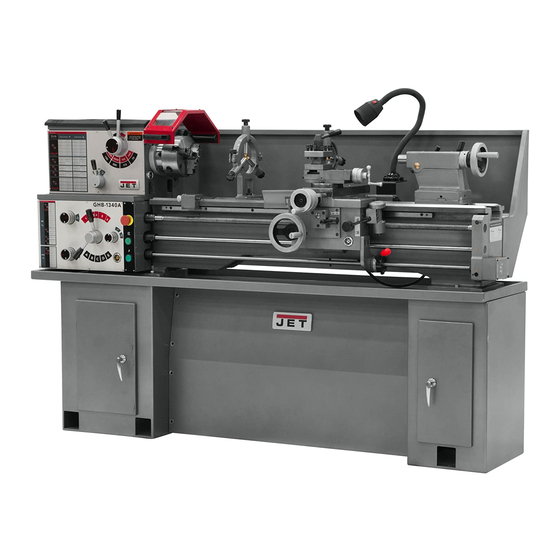
Many thanks for the confidence you have shown in us with the purchase of your new JET-machine. This manual has been
prepared for the owner and operators of a JET GHB-1330/GHB-1340A metal lathe to promote safety during installation,
operation and maintenance procedures. Please read and understand the information contained in these operating instructions
and the accompanying documents. To obtain maximum life and efficiency from your machine, and to use the machine safely,
read this manual thoroughly and follow instructions carefully.
...Table of Contents
1. Declaration of conformity
2. Warranty
3. Safety
Authorized use
General safety notes
Remaining hazards
4. Machine specifications
Technical data
Noise emission
Contents of delivery
Machine description
5. Transport and start up
Transport and installation
Assembly
Mains connection
Initial lubrication
Starting operation
Break in procedure
6. Machine operation
Controls
Chucking
Tool setup
Spindle speed selection
Turning with auto feed
Thread cutting
Drilling operation
7. Setup and adjustments
Change gear setup
Turning between centres
Taper turning with tailstock
Taper turning with top slide
Three jaw universal chuck
Four jaw independent chuck
Live centre
Steady and follow rest
Bed gap removal
8. Maintenance and inspection
Annual lubrication
Weekly lubrication
Daily lubrication
Slide adjustments
Saddle adjustment
Shear pin replacement
Headstock alignment
9. Trouble shooting
10. Environmental protection
11. Available accessories
1. Declaration of conformity
On our own responsibility we hereby
declare that this product complies with
the regulations* listed on page 2.
Designed in consideration with the
standards**.
2. Warranty
The Seller guarantees that the
supplied product is free from material
defects and manufacturing faults. This
warranty does not cover any defects
which are caused, either directly or
indirectly, by incorrect use,
carelessness, accidental damage,
repair, inadequate maintenance or
cleaning and normal wear and tear.
Guarantee and/or warranty claims
must be made within twelve months
from the date of purchase (date of
invoice). Any further claims shall be
excluded.
This warranty includes all guarantee
obligations of the Seller and replaces
all previous declarations and
agreements concerning warranties.
The warranty period is valid for eight
hours of daily use. If this is exceeded,
the warranty period shall be reduced
in proportion to the excess use, but to
no less than three months.
Returning rejected goods requires the
prior express consent of the Seller and
is at the Buyer's risk and expense.
Further warranty details can be found
in the General Terms and Conditions
(GTC). The GTC can be viewed at
www.jettools.com or can be sent by
post upon request.
The Seller reserves the right to make
changes to the product and
accessories at any time.
3
3. Safety
3.1 Authorized use
This metal lathe is designed for
turning and drilling machinable metal
and plastic materials only. Machining
of other materials is not permitted and
may be carried out in specific cases
only after consulting with the
manufacturer.
Never cut magnesium-
high danger to fire!
The workpiece must allow to safely be
loaded and clamped.
The proper use also includes
compliance with the operating and
maintenance instructions given in this
manual.
The machine must be operated only
by persons familiar with its operation
and maintenance and who are familiar
with its hazards.
The required minimum age must be
observed.
The machine must only be used in a
technically perfect condition.
When working on the machine, all
safety mechanisms and covers must
be mounted.
In addition to the safety requirements
contained in these operating
instructions and your country's
applicable regulations, you should
observe the generally recognized
technical rules concerning the
operation of metalworking machines.
Any other use exceeds authorization.
In the event of unauthorized use of the
machine, the manufacturer renounces
all liability and the responsibility is
transferred exclusively to the operator.
3.2 General safety notes
Metalworking machines can be
dangerous if not used properly.
Therefore the appropriate general
technical rules as well as the following
notes must be observed.
Advertisement
Chapters
Table of Contents

Related Manuals for Jet GHB-1330


Summary of Contents for Jet GHB-1330
- Page 1 Dear Customer, Many thanks for the confidence you have shown in us with the purchase of your new JET-machine. This manual has been prepared for the owner and operators of a JET GHB-1330/GHB-1340A metal lathe to promote safety during installation, operation and maintenance procedures.
- Page 2 4.1 Technical data and grease. rest. GHB-1330: Stay alert! Avoid small chucking diameters at big Swing over bed 330mm Give your work undivided attention.
- Page 3 GHB-1330/ GHB-1340A: GHB-1340A: Spindle taper MT-5 Machine cabinet stand Spindle nose DIN 55029 D1-4 Chip tray (Camlock) Splash guard ∅38 mm 160mm 3-jaw universal chuck Hole through spindle 200mm 4-jaw independent chuck Spindle speeds…8 70-2000 rpm 300mm faceplate Tailstock ram travel...
- Page 4 The spindle jog button (B, Fig 5) Caution: 6.1 Controls advances the spindle momentarily. The machine is heavy! The emergency stop button (A, Fig 5) GHB-1330…...600kg stops all machine functions. GHB-1340A….650kg Attention: Assure the sufficient load capacity Lathe still has electric power.
- Page 5 Fig 9 Carefully remove the chuck form the spindle. Fig 7 Fig 11 Clean all contact surfaces. A….Longitudinal Travel Hand Wheel Lift the chuck up to the spindle nose B….Automatic feed lever and press onto the spindle. C….Half-Nut Lever (thread cutting) Tighten in place by turning the cam locks ¼...
- Page 6 6.4 Spindle speeds selection 6.5 Turning with auto feed For example: Longitudinal OD-turning, mild steel of The correct spindle speed depends on Several automatic longitudinal and 25mm diameter with a carbide tool at the type of machining, the cutting cross feeds (see Fig 15) are readily 1255 RPM and with rigid chucking.
- Page 7 - Start the machine at the lowest 7.3 Taper turning with tailstock spindle speed. Turning up to a side angle of 5° can - When the tool reaches the end of be achieved by off-setting the cut, stop the motor and at the same tailstock.
- Page 8 This chuck has four independently Drain oil after first month of adjustable chuck jaws. These permit operation by removing drain plug (B, the holding of square and Fig 23). asymmetrical pieces and enable the Clan out any metal shavings. accurate concentric set-up of Refill with oil.
- Page 9 8.2 Weekly Lubrication: - Tailstock 8.4 Slide adjustments Lubricate 3 ball oilers (I, Fig 26) Weekly inspect the oil sight glasses, Each slide is fitted with tapered gib. fill oil on demand (see 8.1). - Lead screw/ feed rod hub Loosen the rear gib screw (C, Fig 27) Lubricate 3 ball oilers (J, Fig 26) by one turn.
- Page 10 Reduce spindle speed. Article No: 321430 *Workpiece deflection- 200mm 4-jaw independent chuck improve chucking length or diameter, support on tailstock end. Refer to the Jet-Pricelist for various *Tool deflection- accessories. reduce tool length. *Slide backlash- adjust slide gibs. *Slides running dry- lubricate with oil.
-
Page 11: Table Of Contents
Gebrauchsanleitung Sehr geehrter Kunde, vielen Dank für das Vertrauen, welches Sie uns beim Kauf Ihrer neuen JET-Maschine entgegengebracht haben. Diese Anleitung ist für den Inhaber und die Bediener zum Zweck einer sicheren Inbetriebnahme, Bedienung und Wartung der Metalldrehbank GHB-1330 / GHB-1340A erstellt worden. Beachten Sie bitte die Informationen dieser Gebrauchsanleitung und der beiliegenden Dokumente. -
Page 12: Allgemeine Sicherheitshinweise
Die Maschine darf nur in technisch Tragen Sie Schutzschuhe, keinesfalls Arbeiten Sie nie bei geöffnetem einwandfreiem Zustand betrieben Freizeitschuhe oder Sandalen. Bohrfutterschutz oder Riemenschutz. werden. Verwenden Sie die durch Vorschriften Entfernen Sie vor dem Start den Beim Arbeiten an der Maschine geforderte persönliche Drehfutterschlüssel und andere müssen alle Sicherheitseinrichtungen... -
Page 13: Restrisiken
A….Schlosskasten Stehlünette Durchm. 6 – 67mm Lauflünette Durchm. 6 – 70mm B….Reitstock Abmessungen 1905 x 760 x 1200mm C….Leitspindel Maschinengewicht 650 kg D….Zugspindel E….Vorschubgetriebe GHB-1330/ GHB-1340A: F….Stehlünette Spindelkegel MK-5 Spindel DIN 55029 (Camlock) D1-4 G….Mitlauflünette ∅38 mm Spindeldurchlass Geschwindigkeiten..8 70-2000U/min... -
Page 14: Transport Und Inbetriebnahme
Achtung: Fig 3 Mit dem Spindel Schalthebel (I, Fig 6) Die Maschine ist schwer! kann die Spindel gestartet werden. H….Räderdeckel GHB-1330…...600kg - nach rechts und unten für Vorlauf GHB-1340A….650kg I…..3-Achs-Positionsanzeige - nach rechts und oben für Rücklauf (optional) Achten Sie auf ausreichende Bringen Sie den Schalter in Tragfähigkeit und einwandfreien... -
Page 15: Bedienelemente
Halten Sie mit ihren Fingern ausreichend Abstand zu rotierenden Teilen und Spänen. Späne nur bei Maschinenstillstand und mit Hilfe eines geeigneten Spänehakens entfernen. Arbeiten Sie nie bei geöffnetem Futterschutz oder Räderdeckel. Gewindebohren, Gewindeschneiden und das Zerspanen unwuchtiger Werkstücke nur bei niedriger Drehzahl vornehmen. -
Page 16: Einspannen Des Drehmeißels
Die Markierung der Spannexcenter (A) Stahl (C15): 800 U/min muss sich zwischen den 2 Stahl (C45): 600 U/min Pfeilmarkierungen (B) befinden. Falls nicht sind die Spannmittel- Rostfreier Stahl: 300 U/min Camlockbolzen je nach Bedarf um Bei Verwendung von eine Umdrehung ein- oder Schnellarbeitsstahl (HSS) auszuschrauben. -
Page 17: Gewindeschneiden
- Starten Sie die Maschine mit der Zum Beispiel: langsamsten Drehzahl. Außenzerspanung eines gut - Bei Schnittende stoppen Sie den eingespannten 25mm Werkstücks aus Motor und bringen gleichzeitig mittels Stahl (C15) mit einem HM Werkzeug bei 1255 U/min. Querschlittenhub den Gewindestahl außer Eingriff (Achtung Nachlauf: Stoppen Sie den Motor rechtzeitig) Schruppzerspanung:... -
Page 18: Drehen Zwischen Spitzen
Schmieren Sie die Reitstock Wenden Sie die Aufsatzbacken zum Die Stromzufuhr durch Ziehen des Körnerspitze um ein Verreiben zu Spannen großer Durchmesser. Netzsteckers trennen. verhindern. Als Gleitmittel für die Backen Lösen Sie die Sicherungsschraube 7.3 Konusdrehen mit Reitstock empfehlen wir Molykote Paste G, oder und öffnen Sie die Riemenabdeckung. -
Page 19: Wartung Und Inspektion
Ziehen Sie den Kegelstift (B, Fig 21) Der Ölstand muss bis zur Markierung Der Ölstand muss bis zur Markierung durch anziehen der Muttern (A). der Ölstandsanzeige (A, Fig 22) der Ölstandsanzeige (A, Fig 24) reichen. reichen. Entfernen Sie die 4 Schrauben (C). Die Nachfüllung erfolgt an der Die Nachfüllung erfolgt an der Die Bettbrücke kann nun abgehoben... -
Page 20: Schmierung Täglich
8.3 Schmierung täglich: 8.6 Scherstiftwechsel Leit- und Zugspindel sind mit Täglich ölen: Scherstiften versehen um den Antrieb DIN 51502 CG ISO VG 68 bei Überlast zu Schützen. (z.B. BP Maccurat 68, Castrol Magna BD 68, Mobil Vectra 2) Sollte ein Scherstift brechen, so ist er durch einen neuen zu ersetzen - Vorschub Schalthebel Ölen des Schmiernippels (C, Fig 24) -
Page 21: Umweltschutz
*Schnittdruck zu hoch- Artikel Nr: 321430 Spantiefe oder Vorschub reduzieren. 200mm Planscheibe Drehstahl glüht aus *Schnittgeschwindigkeit zu hoch- Drehzahl reduzieren. Siehe auch die Jet Preisliste *Werkzeugschneide verschlissen- Werkzeug schärfen. Maschine dreht konisch *Reitstock ist seitlich versetzt- Reitstock ausrichten. *Maschinenbett ist verdreht- Aufspannflächen müssen eben sein. - Page 22 Nous vous remercions de la confiance que vous nous portez avec l’achat de votre nouvelle machine JET. Ce manuel a été préparé pour l’opérateur du tour à métaux GHB-1330 / GHB-1340A. Son but, mis à part le fonctionnement de la machine, est de contribuer à...
-
Page 23: Consignes De Sécurité
En plus des directives de sécurité Porter des lunettes de protection Tous travaux de branchement et de contenues dans ce mode d’emploi et pendant le travail. des consignes de sécurité en vigueur réparation sur l’installation électrique Placer la machine de sorte à laisser dans votre pays, il faut respecter les un espace suffisant pour la manœuvre règles générales concernant... -
Page 24: Spécifications
Outils de travail dans un coffret Burette à huile Dimensions 1905 x 760 x 1200mm Tiges de levage Poids 650 kg Mode d’emploi GHB-1330/ GHB-1340A: Liste des pièces de rechange Cône de broche CM-5 Broche DIN 55029 (Camlock) D1-4 Fig 2 ∅38 mm Passage d’arbre... -
Page 25: Transport Et Mise En Place
Attention pièce d’œuvre (Voir chapitre 6.2). Fig 3 La machine est lourde ! GHB-1330…...600kg La broche peut être mise en route H….Cache-courroie GHB-1340A….650kg avec le levier interrupteur (I, Fig 6) I…...Affichage de la position – 3 axes - à... -
Page 26: Eléments De Fonctionnement
Garder les doigts à une distance suffisante des éléments en rotation et des copeaux. Ne retirer les copeaux que sur la machine arrêtée et à l’aide d’un crochet spécial. Ne jamais travailler en laissant le protecteur du mandrin ou le cache- roues ouverts. -
Page 27: Choix De La Vitesse
Tendre les pinces excentrées Camlock Lors de l’utilisation d’outils en acíer dans le sens des aiguilles d’une rapide (HSS) la vitesse à choisir est montre. d’env. 1/5 de ces nombres de tours. La marque de la pince excentrée (A) D'une façon générale, on peut dire: en proportion, plus le ∅... -
Page 28: Filetage
- Enclencher la machine avec la Par exemple: vitesse la plus lente. Usinage extérieur d’une pièce d’œuvre - A la fin du filet, arrêter le moteur tout bien serrée en acier (C15) de 25 mm en désengrenant le burin à temps au avec un outil HM par 1255 T/min. -
Page 29: Tournage Entre Les Pointes
Les roues de rechange du coffret Pour le graissage des mors, nous d’outils permettent le filetage de filets conseillons l'usage de pâte Molykote- 7.3 Tournage conique avec la en pouces. G, ou d'une graisse de qualité égale. contre-pointe Couper le courant en retirant la Il est possible de tourner des cônes prise. -
Page 30: Entretien Et Inspection
Dévisser le bouchon qui se trouve Changer l’huile après le premier dessous. Remplir avec de l’huile mois d’exploitation neuve. Dévisser le bouchon (B, Fig 23). Retirer toutes les traces de métaux. A partir de ce moment, changer l’huile Remplir avec de l’huile neuve. une fois par an (le cas échéant, toutes les 700 heures de travail). -
Page 31: Ajustage Des Coulisses Du Chariot
La vis-mère et la broche de chariotage - Levier d’avancement sont munis de goupilles de Huiler le graisseur (C, Fig 24) cisaillement pour protéger - Chariot de table l’entraînement en cas de surcharge. Huiler les 2 graisseurs (D, Fig 24) Si une goupille se casse, il faut la - Chariot supérieur remplacer par une neuve. -
Page 32: Protection De L'environnement
Changer la goupille de cisaillement. de 3-25mm Numéro d´article: 321431 Porte-outil simple Numéro d´article: 321442 Dispositif pour tournage de quilles Numéro d´article: 350055 Dispositif de refroidissement (230V) Option pour GHB-1330: Numéro d´article: 321430 Plateau circulaire 200mm Voir liste de prix JET.
Need help?
Do you have a question about the GHB-1330 and is the answer not in the manual?
Questions and answers