Table of Contents
Advertisement
Advertisement
Table of Contents

Related Manuals for Jet GHB-1236


Summary of Contents for Jet GHB-1236
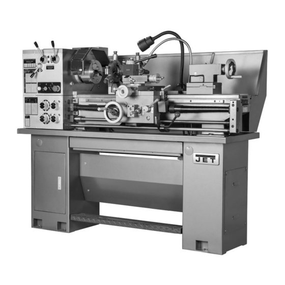
- Page 1 This .pdf document is bookmarked Operation and Maintenance Instructions Geared Head Bench Lathe Model GHB-1236 427 New Sanford Road LaVergne, Tennessee 37086 Part No. M-321236 Ph.: 800-274-6848 Edition 2 05/2019 www.jettools.com Copyright © 2017 JET...
-
Page 2: Important Safety Instructions
14. Make the workshop child proof. Use padlocks, master switches, and remove starter keys. 15. Wear proper apparel. Loose clothing, gloves, neckties, rings, bracelets, or other jewelry may 1.0 IMPORTANT SAFETY get caught in moving parts. Non-slip footwear recommended. Wear protective hair INSTRUCTIONS... -
Page 3: About This Manual
Whatever accepted methods or materials are used, always make personal safety a priority. If there are questions or comments, please contact your local supplier or JET. JET can also be reached at our web site: www.jettools.com. -
Page 4: Table Of Contents
3.0 Table of contents Section Page 1.0 IMPORTANT SAFETY INSTRUCTIONS ....................... 2 2.0 About this manual ............................3 3.0 Table of contents ............................4 4.0 Specifications ..............................6 4.1 Dimensions for provided stand ........................7 5.0 Setup and assembly ............................ - Page 5 13.14.2 Chuck and Leadscrew Guards – Parts List ..................50 13.15.1 Accessories – Exploded View ......................51 13.15.2 Accessories – Parts List ........................52 14.0 Wiring Diagram for GHB-1236 ........................53 15.0 Warranty and service ..........................54 ...
-
Page 6: Specifications
4.0 Specifications Table 1 Model number GHB-1236 Stock number 321236 Motor and Electricals Motor type TEFC induction Horsepower 2 HP (1.5 kW) Phase single Voltage 230V only Cycle 60 Hz Listed FLA (full load amps) 8.5 A Start capacitor 150F 250V Run capacitor 20F 450V... -
Page 7: Dimensions For Provided Stand
= not applicable The specifications in this manual were current at time of publication, but because of our policy of continuous improvement, JET reserves the right to change specifications at any time and without prior notice, without incurring obligations. -
Page 8: Setup And Assembly
5.0 Setup and assembly 5.1 Shipping contents See Figure 5-1. Lathe Steady Rest (mounted on lathe) Follow Rest (mounted on lathe) 6" Three Jaw Chuck (mounted on lathe) 8" Four Jaw Chuck (strapped to container) 10" Face Plate (strapped to container) Tool Box (strapped to container) Chip Tray Splash Guard... -
Page 9: Uncrating And Cleanup
loosen mounting bolts, shim, and retighten 5.2 Uncrating and cleanup mounting bolts. The lathe must be level to be accurate. Machine is heavy. Use an 5.3 Chuck preparation (three jaw) appropriate lifting device and use extreme caution when moving the machine to its final location. -
Page 10: Chuck Guard Installation
5.4 Chuck guard installation Install chuck guard to headstock, if it is not already mounted. (See parts breakdown if clarification is needed for assembly.) 6.0 Lubrication Lathe must be serviced at all lubrication points and all reservoirs filled to operating level before lathe is placed into service. -
Page 11: Electrical Connections
Longitudinal Feed Handwheel – Lubricate ball oiler (H, Figure 6-4) once daily with Mobil The GHB-1236 Lathe is rated at 230-volt power DTE Oil Heavy Medium. only. It is not provided with a power plug; you may either attach a proper 230V UL-listed plug, or “hardwire”... -
Page 12: Extension Cords
This tool is intended for use on a circuit that has an 8.0 General description outlet that looks like the one illustrated in Figure 7- 1. The tool is intended for use with a grounding 8.1 Lathe bed plug that looks like the plug illustrated in Figure 7- 1. -
Page 13: Apron
The sliding fingers are set similar to the steady rest, free of play, but not binding. The sliding fingers require continuous lubrication at the contact points with the workpiece to prevent premature wear. 9.0 Controls Figure 8-2 8.5 Apron The apron (A, Figure 8-2) is mounted to the carriage. - Page 14 Speed Selector Levers (F, Figure 9-1) – Use lock. Turn counterclockwise and loosen to to select spindle speeds in ranges. unlock. Feed Direction Selector (G, Figure 9-1) – Carriage lock screw must Selects carriage travel direction when chuck is be unlocked before engaging automatic rotating in forward direction (or counter- feeds or damage to lathe may occur.
-
Page 15: Operation
feeds and threads under normal circumstances. The additional gears found in the toolbox are used for some metric threads and feeds. Disconnect machine from power source. Open the cover on left end of headstock. Loosen hex nuts (E/F, Figure 10-2). Move quadrant out of the way. -
Page 16: Powered Carriage Travel
Turn knob (B, Figure 10-4) counterclockwise Move the carriage again and adjust if so the arrow is pointing up to start the feed rod necessary. Note: Over-adjustment will cause rotating. excessive, premature wear of gibs. Figure 11-1 Figure 10-4 11.2 Cross slide adjustment 10.5 Powered carriage travel If the cross slide is too loose, follow procedure Push lever (C, Figure 10-3) down to engage cross... -
Page 17: Half Nut Gib Adjustment
Loosen two hex nuts found on the two 11.5 Half nut gib adjustment adjusting bolts located backside headstock just above motor mount bracket. Remove thread dial assembly by unscrewing Adjust the bolts for alignment and tighten hex the screw (D, Figure 11-2). nuts. -
Page 18: Thread And Feed Chart
12.0 Thread and feed chart Table 3... -
Page 19: Replacement Parts
Number of your machine available when you call will allow us to serve you quickly and accurately. Non-proprietary parts, such as fasteners, can be found at local hardware stores, or may be ordered from JET. Some parts are shown for reference only, and may not be available individually. -
Page 20: Headstock Assembly - Exploded View
13.2.1 Headstock Assembly – Exploded View... -
Page 22: Headstock Assembly - Parts List
13.2.2 Headstock Assembly – Parts List Index No. Part No. Description Size 201 .... GHB1236-201 ... Pulley ............... 155x42 ......1 202 .... F006057 ....C-Retaining Ring, Ext ..........60mm ......2 203 .... MFC1000-35 ..... Key, Double Rd Hd ..........A5×12MM ..... 2 204 .... - Page 23 Index No. Part No. Description Size 256 .... F006081 ....C-Retaining Ring, Ext ..........36MM ......1 257 .... F006056 ....C-Retaining Ring, Ext ..........45MM ......1 258 .... F006077 ....C-Retaining Ring, Int ..........42MM ......1 259 .... F006075 ....C-Retaining Ring, Int ..........47MM ......3 260 ....
-
Page 24: Gearbox Assembly - Exploded View
13.3.1 Gearbox Assembly – Exploded View... -
Page 26: Gearbox Assembly - Parts List
13.3.2 Gearbox Assembly – Parts List Index No. Part No. Description Size 301 .... GHB1236-301 ... Cover ......................1 302 .... GHB1236-302 ... Oil Seal ......................1 303 .... GHB1236-303 ... Shaft ......................1 304 .... GHB1236-304 ... Compound Gear ............18T/18T/18T ....2 305 .... - Page 27 Index No. Part No. Description Size 360 .... GHB1236-360 ... Cover ......................2 361 .... GHB1236-361 ... Gear Rack ..................... 1 363 .... GHB1236-363 ... Boss ....................... 4 364 .... GHB1236-364 ... Gear ................. 23T ........ 4 365 ....
-
Page 28: Apron Assembly - Exploded View
13.4.1 Apron Assembly – Exploded View... -
Page 29: Apron Assembly - Parts List
13.4.2 Apron Assembly – Parts List Index No. Part No. Description Size 401 .... GHB1236-401 ... Apron Casting ....................1 402 .... TS-1490051 ....Hex Cap Screw ............M8X30 ......2 403 .... TS-1550061 ....Flat Washer ............. M8 ......... 1 404 .... - Page 30 Index No. Part No. Description Size 461 .... GHB1236-461 ... Cap ........................ 1 462 .... GHB1236-462 ... Shaft ......................1 463 .... BDB919-021 ....Ball Oiler ..............6MM ......1 464 .... GHB1236-464 ... Bracket ......................1 465 ....
-
Page 31: Cross Slide Assembly - Exploded View
13.5.1 Cross Slide Assembly – Exploded View... -
Page 32: Cross Slide Assembly - Parts List
13.5.2 Cross Slide Assembly – Parts List Index No. Part No. Description Size 501 .... GHB1236-501 ... Saddle ......................1 502 .... TS-1533042 ....Phillips Pan Hd Mach Screw ........M5X12 ......8 503 .... GHB1236-503 ... Wiper ......................1 504 .... -
Page 33: Compound Rest Assembly - Exploded View
13.6.1 Compound Rest Assembly – Exploded View... -
Page 34: Compound Rest Assembly - Parts List
13.6.2 Compound Rest Assembly – Parts List Index No. Part No. Description Size 601 .... GHB1236-601 ... Flange Nut ............... M16 ....... 1 602 .... GHB1236-602 ... Handle ......................1 603 .... GHB1236-603 ... Lever ......................1 604 .... GHB1236-604 ... Quick Change Tool Post Body............... 1 605 .... - Page 35 626 .... GHB1236-626 ... Bolt ........................ 1 627 .... GHB1236-627 ... Hex Socket Hd Cap Screw ........M6×25 ......2 628 .... GHB1236-628 ... Bearing Housing .................... 1 629 .... GHB1236-629 ... Long Handle ....................1 630 .... GHB1236-630 ... Index Ring ..................... 1 631 ....
-
Page 36: Tailstock Assembly - Exploded View
13.7.1 Tailstock Assembly – Exploded View... -
Page 37: Tailstock Assembly - Parts List
13.7.2 Tailstock Assembly – Parts List Index No. Part No. Description Size 701 .... GHB1236-701 ... Handle ......................1 702 .... GHB1236-702 ... Handle Screw ....................1 703 .... TS-1540071 ....Hex Nut ..............M10 ....... 2 704 .... TS-1550071 ....Flat Washer ............. M10 ....... 1 705 .... -
Page 38: Change Gears - Exploded View
13.8.1 Change Gears – Exploded View 13.8.2 Change Gears – Parts List Index No. Part No. Description Size 801 .... GHB1236-801 ... Hex Socket Hd Cap Screw ........M6X12 ......2 802 .... GHB1236-389 ... Flat Washer, Large ..........M6 ......... 2 803 .... -
Page 39: Feed Rod Assembly - Exploded View
13.9.1 Feed Rod Assembly – Exploded View... -
Page 40: Feed Rod Assembly - Parts List
13.9.2 Feed Rod Assembly – Parts List Index No. Part No. Description Size 901 .... GHB1236-901 ... Lead Screw ....................1 902 .... GHB1236-902 ... Rod ........................ 1 903 .... GHB1236-903 ... Bracket ......................1 904 .... GB117-6X45 ..... Taper Pin ..............6X45MM ....... 2 905 .... -
Page 41: Motor And Change Gear Enclosure - Exploded View
13.10.2 Motor and Change Gear Enclosure – Exploded View... -
Page 42: Motor And Change Gear Enclosure - Parts List
13.10.2 Motor and Change Gear Enclosure – Parts List Index No. Part No. Description Size 1001 ..GHB1236-1001 ..Change Gear Enclosure ................1 1002 ..GHB1236-1002 ..Door ....................... 1 1003 ..GHB1236-1003 ..Motor Lower Cover ..................1 1004 .. -
Page 43: Stand/Brake/Coolant Pump - Exploded View
13.11.1 Stand/Brake/Coolant Pump – Exploded View... -
Page 45: Stand/Brake/Coolant Pump - Parts List
1155 ..GHB1236-1155 ..Water Tank ....................1 1156 ..GHB1236-1156 ..Connector ...................... 1 1157 ..GHB1236-1157 ..Pump ......................1 1158 ..GHB1236-1158 ..Cover ......................1 ....JET-138 ..... JET Logo (not shown)..........138x57 mm ....1... -
Page 46: Electrical Box Assembly - Exploded View
13.12.1 Electrical Box Assembly – Exploded View... -
Page 47: Electrical Box Assembly - Parts List
13.12.2 Electrical Box Assembly – Parts List Index No. Part No. Description Size 1201 ..GHB1236-1201 ..Circuit Breaker ............DZ47-63 -1PC3 ..... 1 1202 ..GHB1236-1202 ..Circuit Breaker ............DZ47-63-2PD16 .... 1 1203 ..GHB1236-1203 ..Transformer ............. JBK5-100VA-TH ... 1 1204 .. -
Page 48: Steady Rest And Follow Rest - Parts List
13.13.1 Steady Rest and Follow Rest – Parts List... -
Page 49: Steady Rest And Follow Rest - Parts List
13.13.2 Steady Rest and Follow Rest – Parts List Index No. Part No. Description Size 1301 ..GHB1236-1301 ..Pinned Knob ....................3 1302 ..B-56 ......Roll Pin ..............3X20MM ....... 3 1303 ..GHB1236-1303 ..Collar ......................3 1304 .. -
Page 50: Chuck And Leadscrew Guards - Exploded View
13.14.1 Chuck and Leadscrew Guards – Exploded View 13.14.2 Chuck and Leadscrew Guards – Parts List Index No. Part No. Description Size 1501 ..TS-1540041 ....Hex Nut ..............M6 ......... 1 1502 ..F010438 ....Socket Set Screw DP ..........M6 ×16 ......1 1503 .. -
Page 51: Accessories - Exploded View
13.15.1 Accessories – Exploded View... -
Page 52: Accessories - Parts List
13.15.2 Accessories – Parts List Index No. Part No. Description Size 1701 ..GHB1236-1701 ..3-Jaw Chuck Assembly ........... 160MM-D4 ....1 1701-1 ..TS-1503031 ....Hex Socket Hd Cap Screw ........M6X12 ......3 1701-2 ..GHB1236-1701-2 ..Camlock Stud ....................3 1701-3 .. -
Page 53: Wiring Diagram For Ghb-1236
14.0 Wiring Diagram for GHB-1236... -
Page 54: Warranty And Service
JET sells through distributors only. The specifications listed in JET printed materials and on official JET website are given as general information and are not binding. JET reserves the right to effect at any time, without prior notice, those alterations to parts, fittings, and accessory equipment which they may deem necessary for any reason whatsoever. - Page 55 This page intentionally left blank.
- Page 56 427 New Sanford Road LaVergne, Tennessee 37086 Phone: 800-274-6848 www.jettools.com...
Need help?
Do you have a question about the GHB-1236 and is the answer not in the manual?
Questions and answers