Table of Contents
Advertisement
Quick Links
Advertisement
Table of Contents

Related Manuals for ROBBE Arcus V-Tail Prop 1400 ARF


Summary of Contents for ROBBE Arcus V-Tail Prop 1400 ARF
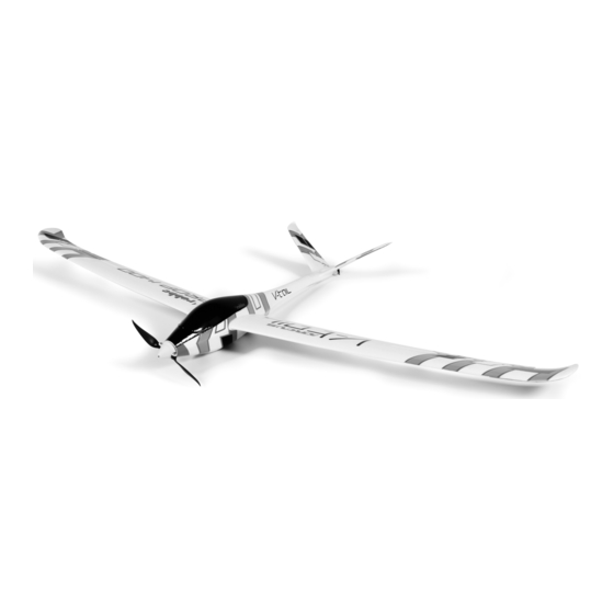
- Page 1 Building and Operating Instructions Arcus V-Tail Prop 1400 ARF No. 2593...
-
Page 2: Table Of Contents
The model vo well covers 2. Selecting the programming point The V-Tail Prop is the latest addition to the robbe Arcus fami- • Factory-assembled propeller and spinner 3. Setting the programming point (value) • Brushless electric motor and speed controller from the robbe ly, and is an eye-catcher in several ways - not just due to its 4. -
Page 3: Radio Control System
Building and Operating Instructions - Arcus V-Tail Prop 1400 No. 2593 Radio control system For this model you require a radio control system with at least four channels. We particularly recommend 2.4 GHz systems. The receiving system is powered by the speed controller’s integral BEC system. -
Page 4: Installing The Tail Panels
Building and Operating Instructions - Arcus V-Tail Prop 1400 No. 2593 Fig. 1 Fig. 2 Fig. 3 - The illustration shows both V-tail panels with the hard pla- - Use Ropoxi 5-minute epoxy to glue the two V-tail panels to - Place the V-tail assembly in the recess in the fuselage. -
Page 5: Installing The Wings
Building and Operating Instructions - Arcus V-Tail Prop 1400 No. 2593 Fig. 7 Fig. 8 Fig. 9 - The illustration shows the V-tail and linkages mounted on - Trim the aileron servo covers to fit flush in the moulded-in - When the covers are a snug fit, attach them to the wings the fuselage. -
Page 6: Installing The Rc System Components
(the orange Insulate each soldered joint with a heat-shrink sleeve. signal wire corresponds to the white wire in robbe-Futaba systems). Place the receiver in the fuselage and deploy the receiver aerial(s). Fig. 17 - On this model the Centre of Gravity “C.G.”... -
Page 7: Checking The Working Systems, Setting Up The Control
Building and Operating Instructions - Arcus V-Tail Prop 1400 No. 2593 Checking the working systems, setting up the control Test-flying, flying notes surfaces Read the sections in the Safety Notes entitled “Routine pre- - Charge the flight battery. flight checks” and “Flying the model” before attempting to fly - Switch the transmitter on, and move the throttle stick to the the model for the first time. -
Page 8: Specification, 20 A Speed Controller
Building and Operating Instructions - Arcus V-Tail Prop 1400 No. 2593 Specification - 20 A speed controller: Programming the speed controller: Continuous current: 20 A (Note: please check that the throttle curve is set to 0%, the throttle stick is at the neutral position, and the Peak current: 25 A, (max. -
Page 9: Replacement Parts List
- You must have operated the product in accordance with the operating instructions. - You must have used recommended power sources and genuine robbe accessories exclusively. - There must be no damage present caused by moisture, unauthorised intervention, polarity reversal, overloading and mechanical stress. -
Page 10: Service Centre Addresses
Modellsport GmbH & Co. KG hereby declares that this device conforms to the fundamental requirements and other relevant regulations of the corresponding EC Directive. You can read the original Conformity Declaration on the Internet at www.robbe.com: click on the "Conformity Declaration" logo button which you will find next to the corresponding device description.
Need help?
Do you have a question about the Arcus V-Tail Prop 1400 ARF and is the answer not in the manual?
Questions and answers