Advertisement
Quick Links
Advertisement

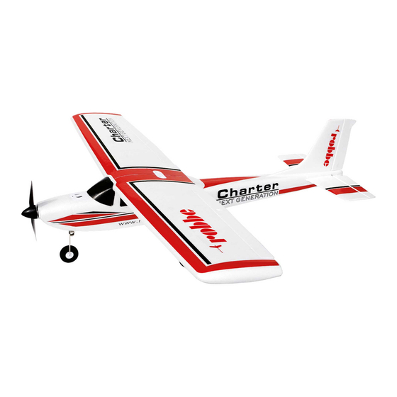
Related Manuals for ROBBE Charter NXG


Summary of Contents for ROBBE Charter NXG
- Page 1 Version No.: 2631 Version No.: 2652 INSTRUCTIONS AND USER MANUAL www.robbe.com V1_05/2019...
- Page 2 Either have it checked by your specialist dealer or in the Robbe Service or have it replaced. In particular, all applicable legal requirements must be observed, which can be found in the roof Hidden faults can occur due to wetness or a crash, which lead to a functional failure after a short associations or the relevant authorities.
- Page 3 • The units have been operated in accordance with the operating instructions. • Keep the battery away from children • Only recommended power sources and original robbe accessories have been used. • Keep leaked electrolyte away from fire, as it is highly flammable and may ignite.
- Page 4 Elevator Charter NXG Vertical axis Transverse axis disconnect the battery first from the ESC, 26310009 BL-Motor 31X28 1350 KV Charter NXG then switch off the transmitter. C.G. = Center of gravity 26310010 Cowling Charter NXG When carrying out any work on the parts...
- Page 5 I N S T R U C T I O N S A N D U S E R M A N U A L Picture 1 - 2 Picture 3 - 7 Install the main landing gear with the Put the prop hub onto the motor shaft.
- Page 6 I N S T R U C T I O N S A N D U S E R M A N U A L Picture 10 Picture 8 Assembly of the tail. Temporarely remove the Make sure that there is a small gap between the securing clips from the linkages.
- Page 7 I N S T R U C T I O N S A N D U S E R M A N U A L Picture 14 - 16 Put the assembled tail on the fuselage and fix it by a M3x22mm screw. Pictures 17 - 19 Connect the elevator and rudder linkage to the outer bore of the...
- Page 8 I N S T R U C T I O N S A N D U S E R M A N U A L Pictures 20 - 22 Wing assembly. Put the carbon wing joiner into the right wing and then put the left wing onto the win joiner and push both halves together.
- Page 9 I N S T R U C T I O N S A N D U S E R M A N U A L Picture 26 - 28 Place the wing on the fuselage by first attaching the two wing plugs to the front of the fuselage.
- Page 10 I N S T R U C T I O N S A N D U S E R M A N U A L Picture 34 - 36 Switch for cargo hatch Picture 34 shows an example of a Mode 2 transmitter for the rudder settings.
- Page 11 I N S T R U C T I O N S A N D U S E R M A N U A L Notes on operation 1. Direction of control surfaces Before the first flight of the model, the direction of all rudders must be checked. Elevator If the elevator stick is pulled back by the transmitter, the elevator must deflect upwards.
- Page 12 I N S T R U C T I O N S A N D U S E R M A N U A L C O N T R O L L E R P R O G R A M M I N G 1.
-
Page 13: Troubleshooting
I N S T R U C T I O N S A N D U S E R M A N U A L 4. Troubleshooting 3. Using the ESC IMPORTANT! Due to different throttle ranges with different remote controls please cali- brate the throttle range before the first flight! Failure Possible cause... - Page 14 I N S T R U C T I O N S A N D U S E R M A N U A L 5. Programming the ESC with the transmitter (4 steps) Note: Please note that the throttle curve is set to 0%, the throttle lever to neutral positi- on and the deflection to 100%.
- Page 15 I N S T R U C T I O N S A N D U S E R M A N U A L F O R Y O U R N O T E S...
- Page 16 4565 Inzersdorf im Kremstal Austria Phone: +43(0)7582/81313-0 Mail: info@robbe.com UID No.: ATU69266037 „robbe Modellsport“ is a registered Trademark by Modellbau Lindinger GmbH Errors, misprints and technical changes reserved. Copyright 2019 Modellbau Lindinger 2019 Copy and reprint only with our permission.
Need help?
Do you have a question about the Charter NXG and is the answer not in the manual?
Questions and answers