Black Box ACS335A User Manual
Kvm-extender for vga, ps2-keyboard/mouse kvm-extender for vga, ps2-keyboard/mouse + serial/audio
Hide thumbs
Also See for ACS335A:
- Specifications (4 pages) ,
- Technical specifications (4 pages) ,
- Quick setup manual (2 pages)
Table of Contents
Advertisement
Quick Links
THE ACS335A KVM-EXTENDER FAMILY
Welcome to the ACS335A KVM-Extender
Family!
Thank you for purchasing a ACS335A KVM-Extender model. We appreciate your business,
and we think you'll appreciate the many ways that your enhanced keyboard/video/ mouse
system will save you money, time, and effort.
That's because our ACS335A KVM-Extender not only allows you to remotely locate a
console (Monitor, Keyboard, Mouse + optional serial/audio devices) over great distances
without any loss in signal quality (up to 1000m/3250ft) but also to do this in an EMI
hazardous environment.
Wherever you have great distances: airports, roller plants, distributed data centres; or in a
range of applications where you have large electromagnetic generators or loads, magnetic
resonance tomographs, induction furnaces, current generators; the ACS335A KVM-Extender
is a solution for remotely locating your console. Two different models cover a range of
applications: a KVM extender for a standard remote console – Monitor, Keyboard and
Mouse; and a second unit with KVM extension and additional serial and bi-directional audio
support. This device is also suitable for computers equipped with a serial mouse or touch
screen.
This manual will tell you all about your new ACS335A KVM-Extender, including how to
install, operate, and troubleshoot it. For an introduction to the Extender,
see Chapter 2. The Extender product codes covered in this manual are:
ACS335A: KVM-Extender for VGA, PS2-Keyboard/Mouse
ACS335A-AS: KVM-Extender for VGA, PS2-Keyboard/Mouse + Serial/Audio
1
Advertisement
Table of Contents

Related Manuals for Black Box ACS335A


Summary of Contents for Black Box ACS335A
- Page 1 This device is also suitable for computers equipped with a serial mouse or touch screen. This manual will tell you all about your new ACS335A KVM-Extender, including how to install, operate, and troubleshoot it. For an introduction to the Extender, see Chapter 2.
-
Page 2: Cautions And Notes
ACS335A –5 STRAND KVM-EXTENDER Copyrights and Trademarks ©2006. All rights reserved. This information may not be reproduced in any manner without the prior written consent of the manufacturer. Information in this document is subject to change without notice and the manufacturer shall not be liable for any direct, indirect, special, incidental or consequential damages in connection with the use of this material. -
Page 3: Federal Communications Commission
FCC/CDC STATEMENTS FEDERAL COMMUNICATIONS COMMISSION AND CANADIAN DEPARTMENT OF COMMUNICATIONS RADIO-FREQUENCY INTERFERENCE STATEMENTS This equipment generates, uses, and can radiate radio-frequency energy, and if not installed and used properly, that is, in strict accordance with the manufacturer’s instructions, may cause interference to radio communication. It has been tested and found to comply with the limits for a Class A computing device in accordance with the specifications in Subpart B of Part 15 of FCC rules, which are designed to provide reasonable protection against such interference when the equipment is operated in a commercial environment. - Page 4 EMPTY PAGE...
- Page 5 This is to certify that, when installed and used according to the instructions in this manual, together with the specified cables and the maximum cable length <3m, the Units: ACS335A ACS335A-AS are shielded against the generation of radio interferences in accordance with the...
- Page 6 SAFETY PRECAUTIONS AND INSTALLATION GUIDELINES Safety Precautions and Installation Guidelines To ensure reliable and safe long-term operation, please note the following installation guidelines: • Only use in dry, indoor environments. • The Remote unit, Local unit and any power supplies can get warm. Do not locate them in an enclosed space without any airflow.
-
Page 7: Table Of Contents
QUICK SETUP Contents 1. Quick Setup 2. Overview Introduction Glossary Features Product Range Compatibility How to Use This Guide 3. Installation Package Contents Interconnection Cable Requirements System Setup Diagnostic and Adjustments 4. Adjustments Jumper Location in the Local Unit Jumper Location in the Remote Unit Customization 5. -
Page 8: Quick Setup
ACS335A –5 STRAND KVM-EXTENDER 1. Quick Setup This section briefly describes how to install your KVM extender system and optimise the video signals. Unless you are an experienced user, we recommend that you follow the full procedures described in the rest of this manual. -
Page 9: Overview
EMI interference may further reduce the maximum distance and reliability. The ACS335A fibre optical KVM Extender System has none of these limitations. Locate your CPU in a secure cabinet or data centre and access it remotely from a distance of up to 1000m. - Page 10 ACS335A –5 STRAND KVM-EXTENDER ACS335A KVM-Extender System Local Access CPU with VGA Graphic Card Optional Serial device + Audio Remote Console ACS335A – KVM Extender System (Example)
-
Page 11: Features
• Transparent serial port (on ACS335A-AS only) enables any serial device to be extended (up to 19.2K Baud). The serial port may be used to extend one device (requiring handshaking lines) or up to three simple serial devices (no handshaking). -
Page 12: Product Range
ACS335A –5 STRAND KVM-EXTENDER 2.4 Product Range There are two products in the range and various options: ACS335A - Extender ACS335A-AS KVM-Extender for VGA, PS2-Keyboard/Mouse Serial/Audio ACS335A KVM-Extender for VGA, PS2-Keyboard/Mouse Extender for VGA only Upgrade Kits ACS253A-RMK 19”/1U Rack Mount Kit (RMK) to mount up to 3 devices... -
Page 13: Compatibility
OVERVIEW 2.5 Compatibility Interface Compatibility • VGA (also called RGBHV): Video signal, consisting of R (red) G (green) and B (blue) signals and the additional horizontal/vertical synchronisation signals. The colour signals have a level of 0.7Vpp, the synchronisation TTL (5Volts). •... -
Page 14: How To Use This Guide
Connection & Compatibility If you have purchased a ACS335A KVM-Extender Kit, this will contain all the cables required to connect the Local unit to your PC or KVM switch. The Remote console (keyboard, monitor and mouse) and any audio and serial equipment connect directly to the Remote unit. -
Page 15: Installation
KVM extender system more conveniently. 3.1 Package Contents You should receive the following items in your extender package: • ACS335A (ACS335A –AS) KVM-Extender Local Unit • ACS335A (ACS335A –AS) KVM-Extender Remote Unit • VGA CPU cable, ZIP type 1,8m (HD15 male / HD15 female, 2 x PS2 male / PS2 male) Models ACS335A-AS and ACS335A •... -
Page 16: Interconnection Cable Requirements
Local Unit/Remote Unit Connection To connect the Local and Remote units you will need: • Multimode Fibre Cable: 5 Fibres 50µm or 62.5µm – ST-plugs. (ACS335A- AS+ACS335A) If you want to use the devices with fibres 62.5 AND the cable length falls short of 300ft/100m, it might be necessary, to reduce the optical budget. -
Page 17: System Setup
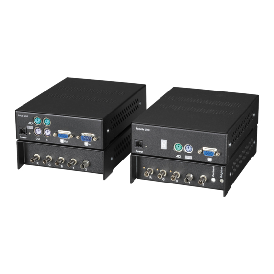
INSTALLATION 3.3 System Setup To install your ACS335A KVM-Extender system: Switch off all devices. Connect your keyboard, monitor, mouse, audio device and serial device to the Remote unit (depending on type of device). Ensure that you attach the keyboard and mouse connectors to the correct ports. - Page 18 Connect to CPU local Monitor VGA socket local Keyboard Keyboard socket Connect to 6V Power supply VGA-Monitor Connectors Keyboard Connectors ACS335A KVM-Extender Type ACS335A-AS Local Unit Audio Connectors 7-Segment display for To the Troubleshooting serial device To the powered To the speakers...
- Page 19 Connect to CPU Keyboard Keyboard socket local Monitor VGA- socket Connect to 6V Power supply PS/2 Connectors VGA Connectors ACS335A KVM-Extender Type ACS335A Local Unit 7-Segment display for Troubleshooting Connect to remote Connect to Connect to Mouse remote Keyboard remote Monitor...
- Page 20 ACS335A –5 STRAND KVM-EXTENDER Fibre connectors (ST) Connectors for Connectors for color signals Digital signals ACS335A KVM-Extender Type ACS335A-AS + ACS335A Local Unit Fibre connectors (ST) Connectors for Connectors for Potentiometer for color signals Digital signals manual gain control Potentiometer for...
-
Page 21: Diagnostic And Adjustments
INSTALLATION 3.4 Diagnostic and Adjustments Each ACS335A KVM-Extender is fitted with an indicator LED Device Ready and a 7- Segment display for enhanced troubleshooting: The Device Ready LEDs are next to the power sockets. The 7-Segment display is next to the power socket of the remote unit. - Page 22 ACS335A –5 STRAND KVM-EXTENDER The location of the 7- Segment display is shown below: 7-Segment display for troubleshooting 7-Segment display on ACS335A Extender 7-Segment Diagnostics Possible cause of fault display Only in mode “AGC-ON” NO error detectable NO error Only in mode “AGC-ON”...
- Page 23 Brightness Brightness/Contrast controls on ACS335A – Extender On each ACS335A KVM-Extender you can adjust Brightness and Contrast manually. You’ll find the potentiometers to the right hand of the fibre connectors on the Remote unit. Please use these potentiometers for adjustment of all colours simultaneously.
- Page 24 ACS335A –5 STRAND KVM-EXTENDER On the front panel of the Remote unit there are potentiometers to adjust the gain of each colour signal. In the mode 'With AGC', these potentiometers have no function. In the mode 'Without AGC' you can adjust the factory setting for the gain of each single colour. This may be necessary if there is a different attenuation between the three lines.
-
Page 25: Adjustments
Carefully displace the lower and upper shells of the case. Model ACS335A-AS carries a Serial/Audio daughter board connected through a flat cable to the main board. Please remove the upper shell carefully to avoid damaging the flat cable. -
Page 26: Jumper Location In The Local Unit
ACS335A –5 STRAND KVM-EXTENDER 4.1 Jumper Location in the Local Unit After unscrewing and opening the upper shell, please place the device in this orientation: with the fibre connectors to the left and the electrical connectors to the right. The main PCB then will look like this:... -
Page 27: Jumper Location In The Remote Unit
ADJUSTMENTS 4.2 Jumper Location in the Remote Unit After unscrewing and opening the upper shell, please place the device in this orientation: with the fibre connectors to the left and the electrical connectors to the right. The main PCB then will look like this: JP20 JP11, JP12 JP1, JP2, JP3... - Page 28 ACS335A –5 STRAND KVM-EXTENDER Changing the graphic source (RGB or VGA) This device can transfer RGB as well as VGA signals. In addition, it is able to do a signal conversation while transferring the signals from RGB to VGA, or from VGA to RGB.
- Page 29 ADJUSTMENTS Using 62.5µ fibre cable The ACS335A KVM-Extender can be used with 50µ or 62,5µ fibre cable. The transmission power must be adjusted to the type of cable. You need not to modify the setting, if at least one of the following two circumstances become true: 1 the cable type is 50µ, 2...
-
Page 30: Monitor Setup
ACS335A –5 STRAND KVM-EXTENDER 5. Monitor Setup This schematic diagram shows the principles of data transmission through the extender system: Normally you should not need to make any modifications. However, under some circumstances, you may want to customize the extenders:... - Page 31 MONITOR SETUP VGA in/RGB out This application uses the extender as a VGA/RGB Converter. The attached monitor must be able to display an RGB signal with the provided frequencies. You can only use an RGB Monitor with a VGA-Signal if the Monitor is able to process the SYNC frequencies (for example, a monitor with HSYNC = 40-90 kHz may not work from VGA with 640x480 = 31,5 kHz).
-
Page 32: Tft Monitors
ACS335A –5 STRAND KVM-EXTENDER 5.1 TFT Monitors Use this procedure to correct for discrepancies in the video signal due to analog/digital video conversion by a TFT monitor. You do not need to follow this procedure if you have a CRT monitor connected because the video format is not converted. -
Page 33: Hints For Pixel Clock And Pixel Phase
MONITOR SETUP 5.2 Hints for Pixel Clock and Pixel Phase Why do you need to adjust Pixel clock and Pixel phase (always in this order) when you are using a TFT screen? This can be explained by means of a 'virtual' reduced system, which has only a few pixels and lines displaying a burst pattern (see above). -
Page 34: Manual Adjustment Of Video Signals
ACS335A –5 STRAND KVM-EXTENDER 5.3 Manual Adjustment of Video Signals CAUTION: This procedure applies to Remote Unit only with AGC=OFF! – do not attempt any adjustment of the Local Unit. The level of the three video signals may be simultaneously adjusted with the Brightness control. -
Page 35: Troubleshooting
TROUBLESHOOTING 6. Troubleshooting There isn’t a picture Check the power supply connection at the Local unit. Is the Device Ready (Red LED) at the Local and Remote unit illuminated? If not, the internal power-supply may be damaged or there may be an internal error (see page 21). Check that the Interconnection cable is connected at the Local Unit and the Remote Unit. -
Page 36: Appendix A: Example Applications
ACS335A –5 STRAND KVM-EXTENDER Appendix A: Example Applications This section illustrates some specific applications using Extender units: • ACS335A KVM-Extender with speaker and microphone. Audio/serial extension Remote console ACS335A KVM-Extender with speaker and microphone... - Page 37 APPENDIX A: EXAMPLE APPLICATIONS • 4 CPU’s – local outputs managed through a KVM- Switch and a single console. Remote Consoles up to 1000m away ACS335A KVM-Extender – local Consoles through a KVM- Switch...
-
Page 38: Appendix B: 19" Rack Mount Options
ACS335A –5 STRAND KVM-EXTENDER Appendix B: 19” Rack Mount Options The ACS335A KVM- Extender units can be mounted in a 19” rack using the ACS253A- RMK. This contains the following parts: Narrow strip Two small blanking plates Wide blanking plate... - Page 39 APPENDIX B: 19” RACK MOUNT OPTIONS Mounting examples: The kit allows you to mount various combinations of regular housings. 1. One regular unit (using two small plates) 2. Two regular units (using one small plate) 3. Mounting of three regular units...
-
Page 40: Appendix C: Audio/Serial Upgrade
ACS335A –5 STRAND KVM-EXTENDER Appendix C: Audio/Serial Upgrade The Audio/Serial Upgrade option consists of daughter boards that allow bi-directional stereo audio and a full-duplex serial data link to be sent across the regular interconnection cable in addition to keyboard, mouse and VGA/DVI video. - Page 41 APPENDIX C: AUDIO/SERIAL UPGRADE Audio Interface - Set Up and Operation The audio interface is line-level and is designed to take the output from a sound card (or other line-level) source and be connected to a set of powered speakers at the other end of the link. Stereo audio may be transmitted either way across the link (simultaneously).
-
Page 42: Appendix D: Technical Support
If you are shipping it for repair, please include the Unit’s external power supplies. If you are returning it, please include everything you received with it. Before you ship the Extender back to Black Box for repair or return, contact us to get a Return Authorization (RA) number. -
Page 43: Appendix E: Specifications
APPENDIX E: SPECIFICATIONS Appendix E: Specifications Power Requirements Voltage PSU: 90..240VAC-0.5A-47..63Hz/6VDC-2000 mA Local Unit: approx. 8W Power required Remote Unit without keyboard: approx. 8W Remote Unit with keyboard: approx. 9.5W Interface (Depending on type of device) Video Source/Monitor VGA up to 1280x1024@75Hz PS2 (AT through adaptor) Keyboard Mouse... - Page 44 ACS335A –5 STRAND KVM-EXTENDER Type of Interconnection Cable ACS335A-AS / ACS335A 5 Fibres Multimode, A/DQ(ZN)B2Y 4G50 (Outdoor Breakout cable with protection against rodent) Optical Elements 850nm Center Wavelength Optical budget total (typical) -5 dBm Size and Shipping Weight ACS335A / ACS335A-AS Remote/Local Unit: 7.1”x5.2”x1.7”...
-
Page 45: Appendix I: Connectors
APPENDIX F: CONNECTORS Appendix F: Connectors ACS335A KVM-Extender Connector Pin outs VGA female (Signal Output) VGA male (Signal Input) Signal Signal Signal RED- RED GND GREEN GREEN GND BLUE BLUE GND HSYNC VSYNC SYNC GND Keyboard/Mouse female (Signal Input/Output) Keyboard... - Page 46 ACS335A –5 STRAND KVM-EXTENDER RS232 (only device ACS335A-AS with serial/Audio Upgrade) 9 pin DSUB female (Local Unit) 9 pin DSUB male (Remote Unit) Signal Not connected Not connected Power Signal Earth n.c. +6VDC Housing Shield...
- Page 47 NOTES...
- Page 48 NOTES...
Need help?
Do you have a question about the ACS335A and is the answer not in the manual?
Questions and answers