Table of Contents
Advertisement
DVI-D CATx/Fiber KVM Extenders
Extend DVI-D and USB HID or USB 2.0 over
affordable CATx cable.
Transmit KVM and DVI-D video signals
up to 460 feet over backbone cabling.
Order toll-free in the U.S.: Call 877-877-BBOX (outside U.S. call 724-746-5500)
Customer
FREE technical support 24 hours a day, 7 days a week: Call 724-746-5500 or fax 724-746-0746
Support
Mailing address: Black Box Corporation, 1000 Park Drive, Lawrence, PA 15055-1018
Information
Web site: www.blackbox.com • E-mail: info@blackbox.com
ACS4002A-R2
ACS4004A-R2
ACS4002A-R2-MM ACS4004A-R2-MM ACS4011A-R2-MM
ACS4002A-R2-SM ACS4004A-R2-SM ACS4011A-R2-SM
BLACK BOX
ACS4011A-R2
®
Advertisement
Table of Contents

Related Manuals for Black Box ACS4002A-R2


Summary of Contents for Black Box ACS4002A-R2
-
Page 1: Black Box
Order toll-free in the U.S.: Call 877-877-BBOX (outside U.S. call 724-746-5500) Customer FREE technical support 24 hours a day, 7 days a week: Call 724-746-5500 or fax 724-746-0746 Support Mailing address: Black Box Corporation, 1000 Park Drive, Lawrence, PA 15055-1018 Information Web site: www.blackbox.com • E-mail: info@blackbox.com... -
Page 2: Fcc Statement
We‘re here to help! If you have any questions about your application or our products, contact Black Box Tech Support at 724-746-5500 or go to blackbox.com and click on “Talk to Black Box.” You’ll be live with one of our technical experts in less than 30 seconds. -
Page 3: Instrucciones De Seguridad
El aparato ha sido expuesto a la lluvia; o D: El aparato parece no operar normalmente o muestra un cambio en su desempeño; o El aparato ha sido tirado o su cubierta ha sido dañada. 724-746-5500 | blackbox.com Page 3 ACS4002A-R2... - Page 4 Trademarks Trademarks Used in this Manual Black Box and the Double Diamond logo are registered trademarks of BB Technologies, Inc. Any other trademarks mentioned in this manual are acknowledged to be the property of the trademark owners. 724-746-5500 | blackbox.com...
-
Page 5: Table Of Contents
Other Errors ..................................39 Appendix A: Sample Applications ................................40 Appendix B: Rackmount Options ................................42 Appendix C: Technical Support ..................................46 Appendix D: Supported Video Modes ................................48 Appendix E: Information in Internal DDC ..............................50 Appendix F: Connectors .................................... 51 724-746-5500 | blackbox.com Page 5 ACS4002A-R2... -
Page 6: Specifications
Size — Local and remote: 1.7"H x 4"W x 5.6"D x (4.3 x 10.3 x 14.3 cm) Shipping Size: 8.7"H x 4.3"W x 2.7"D (22 x 11 x 7 cm) Weight — Local and remote: 1.3 lb. (0.6 kg); Shipping: 3.5 lb. (1.6 kg) 724-746-5500 | blackbox.com Page 6 ACS4002A-R2... -
Page 7: Quick Setup
Check PSUs and connection to power outlet Check the CATx – Fiber cable, and its connectors Check settings of the graphic card or boot CPU Figure 1-1. Quick Setup. 724-746-5500 | blackbox.com Page 7 ACS4002A-R2... -
Page 8: Overview
DVI-I (DVI-D/-I + VGA) and one family with USB 2.0 transparent support – CATx, multimode and single-mode. The product codes covered in this manual are: ACS4002A-R2: KVM Extender DVI-D, USB-HID + USB 2.0, CATx ACS4002A-R2-MM: KVM Extender DVI-D, USB-HID + USB 2.0, Multimode ACS4002A-R2-SM: KVM Extender DVI-D, USB-HID + USB 2.0, Single-mode... -
Page 9: Introduction
Human interface devices (HIDs) are units which are used for human access to the CPU. They are a USB-device class of their own (e.g. memory devices etc.). In addition to keyboards and mice, it includes touchscreens, light pens, fingerprint sensors, graphics tablets, etc. 724-746-5500 | blackbox.com Page 9 ACS4002A-R2... - Page 10 Chapter 2: Overview USB Connection Transmitter/Local Unit CATx or Fiber Cable Receiver/Remote Unit USB Connection Figure 2-1: DVI-D/-I CATx – KVM Extender system (example) 724-746-5500 | blackbox.com Page 10 ACS4002A-R2...
-
Page 11: Features
• CPU cables and adapters included. • Rackmount kit available. ACS4002A-R2 family: • Additional USB 2.0 transparent high-speed transmission (requiring an additional CATx cable or fiber pair). Four devices can be attached directly at the Remote Unit—more by using regular USB hubs. -
Page 12: Product Range
2.4 Product Range There are nine products in the range and various upgrade kits: Table 2-2. Products Product Definition ACS4002A-R2 KVM Extender DVI-D, USB-HID + USB 2.0, CATx ACS4002A-R2-MM KVM Extender DVI-D, USB-HID + USB 2.0, Multimode ACS4002A-R2-SM KVM Extender DVI-D, USB-HID + USB 2.0, Single-Mode... -
Page 13: How To Use This Guide
However, the automatic color switching enhances the frame count transmitted per second; fixed 24-bit color depth gives smooth color grades under all circumstances. Choose the one that’s best for your application. To modify the color depth, see 4.0 Service Setup. 724-746-5500 | blackbox.com Page 13 ACS4002A-R2... -
Page 14: Installation
• 6-ft. (1.8-m) USB cable • 6-ft. (1.8-m) DVI-D video cable • User‘s manual with quick-install guide ACS4004A-R2 family (also includes): • 6-ft. (1.8-m) USB cable ACS4011A-R2 family (also includes): • 6-ft. (1.8-m) VGA-to-DVI-D video cable 724-746-5500 | blackbox.com Page 14 ACS4002A-R2... -
Page 15: Interconnection Cable Requirements
There is no guarantee of this, and users are asked to perform tests within their own environments. • Power supply: Connect the supplied 5-VDC power supplies to the plug terminal on the rear of both local and remote units. 724-746-5500 | blackbox.com Page 15 ACS4002A-R2... -
Page 16: System Setup
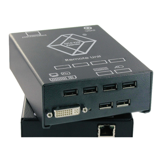
USB connector. 7. Power up the system. Connect to CPU: to CPU: DVI secondary USB Connect to local Connect to CPU: DVI- monitor Figure 3-1. ACS4002A-R2/ACS4002A-R2-xx local unit with 2x USB-HID + 4x USB-2.0. 724-746-5500 | blackbox.com Page 16 ACS4002A-R2... - Page 17 Remote keyboard/ Remote DVI-monitor port— mouse port. connect to remote console monitor. Figure 3-2. ACS4002A-R2/ACS4002A-R2-xx remote unit with 2x USB-HID + 4x USB-2.0. This port carries USB 2.0—connect to local/remote unit with CATx cable. Connect to 5V power supply. This port carries video and data signals—connect it to a local or remote unit with CATX cable.
- Page 18 Figure 3-4. ACS4002A-R2-xx local/remote unit: rear view fiber. Connect to CPU: DVI-I port ‘Eye‘ for IR-RC Programming (DVI-D or VGA) Connect to local DVI- Connect to CPU: USB. monitor. Figure 3-5. ACS4002A-R2/ACS4011A-R2-xx, local unit with DVI-I input (DVI-D + VGA). 724-746-5500 | blackbox.com Page 18 ACS4002A-R2...
- Page 19 Connect to 5-V power supply. CATx cable. Figure 3-7. ACS40011A-R2-xx local unit (CATx): rear view. Connect to local/remote unit with Connect to 5V power supply. fiber cable. Figure 3-8. ACS40011A-R2-xx local unit (fiber): rear view. 724-746-5500 | blackbox.com Page 19 ACS4002A-R2...
- Page 20 Connect to 5V power supply. CATx cable. Figure 3-9. ACS40011A-R2-xx remote unit (CATx): rear view. Connect to local/remote unit with Connect to 5V power supply. fiber cable. Figure 3-10. ACS40011A-R2-xx remote unit (fiber): rear view. 724-746-5500 | blackbox.com Page 20 ACS4002A-R2...
-
Page 21: Diagnostic Leds
No CATx connection Power LED Device ready (Green LED) Device ready Power LED Blinking/on Errors through data transmission over CATx cable (Green LED) (Cable too long, too high attenuation or too much EMI interference) 724-746-5500 | blackbox.com Page 21 ACS4002A-R2... -
Page 22: Service Setup
The main circuit board then will look like this: Location of jumpers: indicated as JP1, JP3, JP3. Figure 4-2. Schematic of the interior of the local unit. Note the position of the jumpers. 724-746-5500 | blackbox.com Page 22 ACS4002A-R2... -
Page 23: Setup At The Local Unit
• The DDC information from the remote monitors will be read automatically, transferred to the local units and stored into the DDC EPROM. • After a successful programming of the DDC EPROM, the “Video-OK“ LED at the local unit will blink rapidly for approximately one second, indicating that you are finished. 724-746-5500 | blackbox.com Page 23 ACS4002A-R2... - Page 24 For the highest color depth at all times (with possibly reduced frame rates), select the 24-bit setting. Table 4-2. Color Depth Settings Color Depth 16-bit/24-bit Autoselect setting. (Default). Otimizes the color depth based on screen content. 24-bit 724-746-5500 | blackbox.com Page 24 ACS4002A-R2...
-
Page 25: Setup At The Remote Unit
Table 4-3. Color Depth Settings Moment to Switch Behavior Higher frame rate, but horizontal breaks may Switching during HSYNC possibly be detectable. (default) Lower frame rate, but no horizontal breaks Switching during VSYNC detectable; possibility of stepping pictures. 724-746-5500 | blackbox.com Page 25 ACS4002A-R2... -
Page 26: Setup For The On Screen Display (Osd-Acs4011A-R2 Only)
Exit OSD Select next position/increase parameter Select previous position/decrease parameter Enter OSD Direct brightness control Direct contrast control Reset to factory defaults (press twice) Back to the menu selection Figure 4-4. Infrared Remote Control (IR-RC). 724-746-5500 | blackbox.com Page 26 ACS4002A-R2... - Page 27 You can adjust the following properties using the OSD: • Auto Configuration ON/OFF • Color, color temperature adjustments • Brightness/contrast • Input image sizing • Output image scaling and sizing • OSD operation, factory reset 724-746-5500 | blackbox.com Page 27 ACS4002A-R2...
- Page 28 Define and size, and the attached display default values. flesh/skin tone, hue, picture size and factory reset. and select one of and saturation. position. four scaling modes. Figure 4-8. OSD menu icons. 724-746-5500 | blackbox.com Page 28 ACS4002A-R2...
- Page 29 Return to the previous menu selection. Open the highlighted menu or submenu; also, accept the command. Select the previous menu or command icon; decrease the highlighted parameter. Select the next menu or command icon; increase the selected parameter. 724-746-5500 | blackbox.com Page 29 ACS4002A-R2...
- Page 30 From the main menu, select the “Brightness/Contrast“ icon to adjust the brightness and contrast of the video image, or to adjust the black level of a display: Adjust Brightness Adjust Contrast Adjust Black level Return to main menu Figure 4-12. Brightness/Contrast adjustment. 724-746-5500 | blackbox.com Page 30 ACS4002A-R2...
- Page 31 For output of 1024 x 768, the maximum input resolution is 1680 x 1050 (Reduced Blanking). For output of 1280 x 1024, all maximum input resolutions are possible. With VGA input signals, there are no limits for up- or downscaling. 724-746-5500 | blackbox.com Page 31 ACS4002A-R2...
- Page 32 Set up colors in RGB space. Automatically adjusts settings in CMY space. Choice of five color temperature settings: 4200 k, 5000 k, 6500 k, 7500 k, and 9300 k. Back to Color menu Figure 4-15. Color Temperature submenu. 724-746-5500 | blackbox.com Page 32 ACS4002A-R2...
- Page 33 When resolution is Selecting color depth (HiColor/LoColor). changed by an imposed fixed resolution, sharpness can be affected. Use this option to switch between three settings for optimum sharpness.. Figure 4-17. Tools menu. 724-746-5500 | blackbox.com Page 33 ACS4002A-R2...
- Page 34 Disable automatic detection of pixels per line and phase after a mode change. Enable automatic detection of pixels per line and phase after a mode change. Back to Tools menu. Figure 4-19. The Auto Configuration submenu, from the Tools menu. 724-746-5500 | blackbox.com Page 34 ACS4002A-R2...
- Page 35 Information in 2.5 How to Use This Guide. Under some circumstances, the local unit should identify itself as a “VGA monitor“ providing DDC information like a VGA screen (DVI-DDC and VGA-DDC are different). In this case, you can convert the internal DDC table to a VGA-DDC by hitting the “Create VGA“ button. 724-746-5500 | blackbox.com Page 35 ACS4002A-R2...
-
Page 36: Setup For Vga Input (Acs4011A-R2 Family)
Return to the OSD utility and select this menu command: Manually adjust the number of pixels per line (pixel clock) from the Image menu. b. Adjust the pixel clock value until all stripes have disappeared. c. Confirm the setting. 724-746-5500 | blackbox.com Page 36 ACS4002A-R2... - Page 37 10. If necessary, adjust the position of the visible part of the screen. It may be necessary to adjust the picture size (Step 9) again. 11. If appropriate, re-attach your TFT monitor and adjust its image according to the manufacturer’s instructions. 724-746-5500 | blackbox.com Page 37 ACS4002A-R2...
-
Page 38: Troubleshooting
How to solve the problem: Use a lower resolution or use a desktop background that is better suitable for compression: avoid photos for background or horizontally graduated colors. Or better yet, use monochrome backgrounds, which allow for higher compression -> higher frame rates. 724-746-5500 | blackbox.com Page 38 ACS4002A-R2... -
Page 39: Usb-Hid Device Errors
You have connected a non-HID device to the HID port. For these ports, only HID devices are supported. (For example, on the ACS4002A-R2 model, there are six total USB ports at the remote unit. The two ports in the lower row are USB-HID only. -
Page 40: Appendix A: Sample Applications
Appendix A: Sample Applications Appendix A: Sample Applications USB Connection Transmitter/Local Unit CATx or Fiber Cable Receiver/Remote Unit USB Connection USB Devices Figure A-1. DVI-D CATx KVM Extender with USB 2.0 support. 724-746-5500 | blackbox.com Page 40 ACS4002A-R2... - Page 41 Appendix A: Sample Applications USB Connection Transmitter/Local Unit CATx or Fiber Cable Receiver/Remote Unit USB Connection Figure A-2. DVI-D CATx KVM Extender supporting VGA and DVI-D. 724-746-5500 | blackbox.com Page 41 ACS4002A-R2...
-
Page 42: Appendix B: Rackmount Options
• Fasten the base of the unit to the plate of the mounting kit. • Close the remaining gaps with blanking plates. NOTE: Use only the supplied short screws to prevent damages on the PCBs 724-746-5500 | blackbox.com Page 42 ACS4002A-R2... - Page 43 NOTE: In the leftmost position, you can install a rackmountable PSU, ACS2209A-PS instead of an extender device. This PSU will enable you to power up to three single- or dual-head devices. Figure B-4. Mounting the optional ACS2209A-PS. 724-746-5500 | blackbox.com Page 43 ACS4002A-R2...
- Page 44 • Fasten the base of the unit to the plate of the mounting kit. • Close the remaining gaps with blank plates. NOTE: Use only the supplied short screws to prevent damages on the circuit boards. 724-746-5500 | blackbox.com Page 44 ACS4002A-R2...
- Page 45 NOTE: In the leftmost position, you can install a rackmountable power supply unit (PSU) (ACS2209A-PS) instead of an extender device. This PSU will enable you to power up to three single- or dual-head devices. Figure B-8. Mounting the optional ACS2209A-PS. 724-746-5500 | blackbox.com Page 45 ACS4002A-R2...
-
Page 46: Appendix C: Technical Support
• If you are shipping it for repair, please include the exender’s external power supplies. If you are returning it, please include everything you received with it. Before you ship the extender back to Black Box for repair or return, contact Tech Support to get a return authorization (RA) number. - Page 47 Appendix C: Technical Support Black Box Technical Support Table C-1. Black Box Technical Support Contact Information. Country Web Site and Email Phone www.blackbox.com info@blackbox.com 724-746-5500 724-746-0746 www.black-box.at Austria support@black-box.at +43 1 256 98 56 +43 1 256 98 56 www.blackbox.be support.english@blackbox.be...
-
Page 48: Appendix D: Supported Video Modes
1280 60.0 48.1 81.2 WXGA 1280 60.2 47.8 80.0 WXGA 1280 59.8 49.7 83.5 WXGA 16:10 CVT 1280 60.0 60.0 108.0 VESA Standard 1280 75.0 75.0 126.0 DMT127A 1280 85.0 85.9 148.5 VESA Standard 724-746-5500 | blackbox.com Page 48 ACS4002A-R2... - Page 49 60.0 65.3 146.3 WSXGA+ 16:10 VGA 1920 1080 50.0 56.4 148.5 TV Mode 16:9 1920 1080 59.9 66.6 138.5 TV Mode 16:9 1920 1080 60.0 67.5 148.5 EIA861B16:9 1920 1200 60.0 74.0 154.0 WUXGA 724-746-5500 | blackbox.com Page 49 ACS4002A-R2...
-
Page 50: Appendix E: Information In Internal Ddc
1680 x 1050 60 Hz 119 MHz 1600 x 1200 60 Hz 162 MHz 1920 x 1200 50 Hz 148.5 MHz 1920 x 1200 60 Hz 148.5 MHz 1920 x 1200 60 Hz 154 MHz 724-746-5500 | blackbox.com Page 50 ACS4002A-R2... -
Page 51: Appendix F: Connectors
Appendix F: Connectors DVI-D/-I CATx/Fiber KVM-Extender Connector Pinouts C1 C2 C3 C4 Figure F-1. DVI-I female connector (Output connector for all devices and Input connector for the ACS4002A-R2 device - local unit). Table F-1. DVI-I Female Connector. Signal Signal Signal... - Page 52 Appendix F: Connectors DVI-I Female Input Connector for the ACS4011A-R2 Local Unit C1 C2 C3 C4 Figure F-2. DVI-I female connector (Input connector for the ACS4002A-R2 local unit). Table F-2. DVI-I Female Connector. Signal Signal Signal TMDS data 2- TMDS data 1-...
- Page 53 1 2 3 4 Figure F-4. USB Connector at the Remote Unit, USB Type A. Table F-4. USB Connector at the Remote Unit. Signal VCC (+5V) Data - White Data + Green Ground Black 724-746-5500 | blackbox.com Page 53 ACS4002A-R2...
- Page 54 Figure F-5. 1000BASE-T Pinout. Table F-5. USB Connector at the Remote Unit. Programming Port Figure F-6. Programming Port. Table F-6. Programming Port Pinout. Signal TxD (to PC RxD) RxD (from PC TxD) DTR from PC Ground- 724-746-5500 | blackbox.com Page 54 ACS4002A-R2...
- Page 55 Notes 724-746-5500 | blackbox.com Page 55 ACS4002A-R2...
- Page 56 About Black Box Black Box Network Services is your source for an extensive range of networking and infrastructure products. You’ll find everything from cabinets and racks and power and surge protection products to media converters and Ethernet switches all supported by free, live 24/7 Tech support available in 30 seconds or less.
Need help?
Do you have a question about the ACS4002A-R2 and is the answer not in the manual?
Questions and answers