Table of Contents
Advertisement
HP UPS Network Module
User Guide
Abstract
This document includes installation, configuration, and operation information for the HP UPS Network Module. This document is for the person who
installs and maintains power products. HP assumes you are qualified in the servicing of high-voltage equipment and trained in recognizing hazards
in products with hazardous energy levels.
Part Number: 637918-001
June 2011
Edition: 1
Advertisement
Table of Contents

Related Manuals for HP UPS Network Module


Summary of Contents for HP UPS Network Module
-
Page 1: User Guide
Abstract This document includes installation, configuration, and operation information for the HP UPS Network Module. This document is for the person who installs and maintains power products. HP assumes you are qualified in the servicing of high-voltage equipment and trained in recognizing hazards in products with hazardous energy levels. - Page 2 © Copyright 2011 Hewlett-Packard Development Company, L.P. The information contained herein is subject to change without notice. The only warranties for HP products and services are set forth in the express warranty statements accompanying such products and services. Nothing herein should be construed as constituting an additional warranty. HP shall not be liable for technical or editorial errors or omissions contained herein.
-
Page 3: Table Of Contents
Connecting the network cable ........................13 Connecting the configuration cable ......................14 Launching a terminal emulation program ....................14 Configuring the UPS Network Module network settings ................15 HP UPS Network Module web interface ..................16 HP UPS Network Module web interface overview ..................16 Accessing the web interface ........................ - Page 4 Client communication failure with HP UPS Network Module in a VMware operating system ......75 Client server is not restarting ........................75 Clients cannot communicate with UPS after swapping HP UPS Network Module with another UPS ..... 75 Failure to communicate with the serial or USB ports ..................75 Forgot login password ..........................
- Page 5 FCC rating label ..........................78 Class A equipment......................... 78 Class B equipment ......................... 78 Declaration of conformity for products marked with the FCC logo, United States only ........79 Modifications ............................79 Canadian notice (Avis Canadien) ......................79 European Union regulatory notice ......................80 Disposal of waste equipment by users in private households in the European Union .........
-
Page 6: Overview
For a detailed list of supported UPSs, see the HP website (http://www.hp.com/go/rackandpower). Features The UPS Network Module is a minislot card that requires UPSs equipped with a minislot. The UPS Network Module: • Monitors the status, performs UPS diagnostics, and transmits periodic reports. -
Page 7: Hp Power Protector Overview
Install the HPPP Client on any machine that is powered by the UPS and any machine that the UPS Network Module uses to initiate a shutdown command. -
Page 8: Configuration B
UPS Network Modules over the network to begin a graceful shutdown in the event of a power failure or other configured shutdown events. NOTE: Up to 35 HPPP Clients can be managed by one HP UPS Network Module. Overview 8... -
Page 9: Web Interface Requirements
Remote workstation browsing into the UPS Network Module or HPPP Client over the network Power connection Green Communication path Web interface requirements The following table lists the minimum requirements necessary to operate the UPS Network Module web interface. Software Browser Internet Explorer •... -
Page 10: Quick Installation And Setup Overview
Install and configure the HPPP Client on all servers to be protected by the UPS. After all Clients are configured at the servers, they are automatically added by the UPS Network Module and appear on the Notified Applications screen (on page 40). -
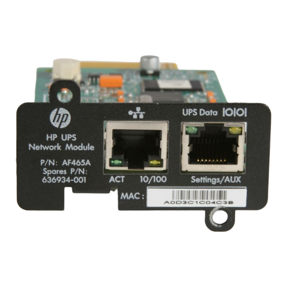
Page 11: Component Identification
Connector/LED Description Network connector Ethernet port Network Activity LED • Off—UPS Network Module not connected to the network • Solid green—UPS Network Module connected to the network, but no activity detected • Flashing green—UPS Network Module connected to the network... -
Page 12: Installing The Hp Ups Network Module
Installing the UPS Network Module NOTE: It is not necessary to power down the UPS before installing the UPS Network Module. Remove the two screws securing the UPS option slot cover plate and slide the plate out. Install the UPS Network Module along the alignment channels in the option slot. -
Page 13: Connecting The Network Cable
If the UPS is powered up, you can be sure that the UPS Network Module is seated properly and communicating with the UPS by verifying that the UPS Data LED illuminates solid green, and then flashes regularly after 2 minutes. -
Page 14: Connecting The Configuration Cable
Connect the RJ-45 connector on the DB-9 to RJ-45 cable to the Settings/AUX connector on the UPS Network Module. This connection is used to access and configure the UPS Network Module network settings locally through a terminal emulation program. Launching a terminal emulation program NOTE: HyperTerminal is the serial communication program provided with Microsoft®... -
Page 15: Configuring The Ups Network Module Network Settings
Enter 0 to return to the Main menu. Enter 1 to reset the UPS Network Module, and then enter 2 to restart the UPS Network Module with the new IP settings. Installing the HP UPS Network Module 15... -
Page 16: Hp Ups Network Module Web Interface
HP UPS Network Module web interface overview The web interface graphically displays various measurements and warning and alarm messages from the UPS Network Module. Also, system values and power fail settings can be configured through the web interface and saved to the UPS Network Module. -
Page 17: Browser Security Alert
The encrypted channel ensures the integrity of the data between the web server and the browser, so that data can neither be viewed nor modified while in transit. The UPS Network Module uses a system generated and unique key. -
Page 18: Establishing A Secure Session For Mozilla
UPS Network Module: Click Examine Certificate. Verify that the name in the Issued To field is the name or IP address of your UPS Network Module. Perform any other steps necessary to verify the identity of the UPS Network Module. -
Page 19: Establishing A Secure Session For Google Chrome
Browse to the UPS Network Module through a secure connection. The certificate appears with a warning. Click Proceed anyway, and then login to the UPS Network Module web interface. Navigating the web interface The web interface is divided into two frames: •... -
Page 20: Power Source Screen
UPS components and the electrical flow powering the load If communication with the UPS is lost, the diagram appears gray. Diagrams do not display for line-interactive UPSs. • UPS measurements—A popup box that displays UPS data details HP UPS Network Module web interface 20... - Page 21 UPS without automatic bypass The following table describes the possible diagram elements. Diagram element Description AC Normal Input Green—In tolerance Gray—Out of tolerance AC Normal Flow Yellow—AC to DC converter powered by normal AC HP UPS Network Module web interface 21...
- Page 22 Gray—Not powered Red—Internal failure DC to AC Converter Output Yellow—Energy flow present Gray—No energy flow AC Bypass Input Green—In tolerance Red—Out of tolerance AC Automatic Bypass Flow Yellow—Energy flow present Gray—No energy flow HP UPS Network Module web interface 22...
-
Page 23: Ups Status Table
About your UPS ("About your UPS table" on page 24)—Provides information about the model range and software version of the UPS and the UPS Network Module UPS Status table The UPS Status table displays the following basic information about power and output: •... -
Page 24: Ups Alarms Table
Card Hardware Revision—The hardware version for the UPS Network Module Card Serial Number—The serial number for the UPS Network Module Card Ethernet MAC Address—The MAC address for the UPS Network Module Card Ethernet Speed—The port speed of the UPS Network Module... -
Page 25: Manual Control Screen
Delayed, safe power down—A shutdown sequence for the load segment is launched when the Off Delay time is reached. Connected equipment powers off, and then the load segment powers off. HP UPS Network Module web interface 25... -
Page 26: Schedule Shutdown Screen
NOTE: In a redundant configuration, do not set both UPS Network Modules to shut down at the same time. Set the Shutoff Times 30 minutes apart so that HP Power Protector can perform a graceful shutdown. HP UPS Network Module web interface 26... -
Page 27: Logs
Click UPS Data Log in the menu tree to display the UPS Data Log screen. This screen displays a log of UPS data collected by the UPS Network Module. The frequency at which data is collected can be modified on the System Settings screen (on page 30). -
Page 28: Event Log Screen
UPS, such as the UPS switching to battery power. NOTE: In the UPS Data Log and the Event Log, the date and time stamps are converted to the local time zone. The following information is displayed for each event: HP UPS Network Module web interface 28... -
Page 29: System Log Screen
Click System Log in the menu tree to display the System Log screen. This screen displays a log of the events that have occurred on the UPS Network Module, such as a communication failure or system shutdown. The following information is displayed for each event: •... -
Page 30: Settings
49 characters. Enter a description of the physical location of the UPS in the UPS Location field. This text field is limited to 31 characters. The UPS Location displays throughout the interface. HP UPS Network Module web interface 30... -
Page 31: Access Control Screen
5 and 99999 seconds. By default, UPS data is collected every 60 seconds. Click Save. To perform a remote reboot of the UPS Network Module without modifying the configuration, click Reset Communication. This action is required to enable any changes made on the Network Settings screen (on page 32). -
Page 32: Network Settings Screen
To configure the network settings: Select Enabled from the BootP/DHCP pull-down menu to allow configuration of network parameters by a BootP or DHCP server. After each restart, the UPS Network Module makes five attempts to recover the HP UPS Network Module web interface 32... - Page 33 Enter the host name of the UPS Network Module in the Hostname field. The host name is the first part of the fully qualified domain name used by the DNS. The host name is sent to the DNS only if the DHCP server sends the host name with the new IP address.
-
Page 34: Time Settings Screen
Verify that the HPPP Client is configured with the correct date and time, because the UPS Network Module uses the time from the first Client that responds. Select the Accept automatic update from HP Power Protector radio button. Click Save. -
Page 35: Shutdown Parameters Screen
Click Save to connect to the NTP server and set the date and time. The UPS Network Module uses the NTP protocol (UDP 123 port). The firewall must be set to transmit queries outside the network. No error message is generated if connection with the NTP server fails. The UPS Network Module attempts to connect to the NTP server every 10 seconds until a connection is made. - Page 36 In the Shutdown initiated after field (individual load segments), enter the number of seconds after the power fails that the UPS Network Module should wait before starting to shut down the load segment (0 to 99999 seconds, 300 seconds by default). Enter a shorter delay for load segments that power less critical equipment to preserve UPS battery power for other load segments.
- Page 37 (0 to 100%, 20% by default). The UPS Network Module initiates a load segment shutdown when the remaining battery life reaches the specified percentage.
- Page 38 0% by default). In the Switch on after the restart (individual load segments), enter the number of seconds after the UPS restarts that the UPS Network Module should wait before restarting the load segment (from HP UPS Network Module web interface 38...
-
Page 39: Snmp Settings Screen
SNMP Settings screen Click SNMP in the menu tree to display the SNMP Settings screen. This screen allows an administrator to configure SNMP settings for computers that use the HP Power MIB to request information from the UPS Network Module. -
Page 40: Notified Applications Screen
NOTE: To query SNMP data, you do not need to add SNMP Manager. The following information is available on the Notified Applications screen: • Nr—The assigned application number in the Notified Applications list HP UPS Network Module web interface 40... - Page 41 To simulate a utility power failure: Select the checkbox for the application you want to test. To select all applications, click All. Click Utility Failure Test. The UPS Network Module sends a Utility failure trap, and then sends a Utility restored trap 30 seconds later.
-
Page 42: Email Notification Screen
UPS Network Module. SNMP management applications, such as HP Systems Insight Manager, can receive notifications from the UPS Network Module. Up to three applications can be configured to receive SNMP traps from the UPS Network Module. To configure an application to receive SNMP traps: Enter the name of the application in the Application Name field. - Page 43 SMS standard for text messaging. The required format might vary, depending on the cellular service provider. Contact your cellular service provider for mail to SMS gateway settings. Up to four recipients can be configured to receive email notifications from the UPS Network Module. To configure a recipient of email notifications: Enter the email address of the recipient in the Recipient field.
- Page 44 UPS name—Includes the name of the UPS in the email subject when selected UPS location—Includes the geographic location of the UPS in the email subject when selected Event message—Identifies the event generating the message in the email subject when selected HP UPS Network Module web interface 44...
-
Page 45: Firmware Upload Screen
Click Firmware Upload in the menu tree to display the Firmware Upload screen. This screen allows an administrator to upgrade the UPS Network Module firmware. During the upgrade process, the UPS Network Module does not monitor the UPS status. To upgrade the firmware: Download the latest firmware version from the HP website (http://www.hp.com/go/rackandpower). -
Page 46: Hp Ups Network Module Configuration Menu
HP UPS Network Module Configuration Menu overview The HP UPS Network Module Configuration Menu provides an alternative, limited interface to the UPS Network Module. System network values can be configured through the Configuration Menu and saved to the UPS Network Module. -
Page 47: Reset Submenu
Enables you to change IPv4 network settings for the UPS Network Module Set Ethernet Speed Enables you to configure the port speed for the RJ-45 Ethernet network connector Exit Returns to the previous menu HP UPS Network Module Configuration Menu 47... -
Page 48: Systems Insight Manager Integration
For example, if the UPS Network Module detects an alarm condition, the module can send a trap to HP SIM with an attached hyperlink that routes users directly to the web interface for the attached UPS. -
Page 49: Discovering The Ups Network Module
HP SIM automatically detects UPS Network Modules as part of the device discovery process. If detected, a hyperlink is included on the HP SIM All Systems page for the UPS on which the UPS Network Module is installed. The UPS Network Module should be installed and running before attempting discovery through HP SIM. -
Page 50: Configuring Hp Sim To Receive Traps
Configuring the UPS Network Module to send traps to HP SIM Add the HP SIM server as an SNMP trap recipient on the Trap Receivers Settings screen (on page 42). The configured server appears on the Notified Applications screen (on page 40). -
Page 51: Optional Power Monitoring Using Snmp
To query SNMP data, you do not need to add SNMP Mangers to the Notified Application page. In the third-party SNMP manager, configure the IP address of the UPS Network Module, select SNMP V1 or V1&V3, and then compile either CPQPOWER.MIB or UPS.MIB (RFC1628) to be monitored by the SNMP manager. -
Page 52: Configuration Parameters
Follow these shutdown principles when configuring the shutdown parameters: • The Shutdown initiated after (SIA) value entered for the UPS Network Module must be equal to or greater than the HPPP Client configured with the longest SIA time. Otherwise, the Client starts to shutdown at the same time as the UPS Network Module. - Page 53 This following example describes the shutdown parameters for a UPS with two load segments, four connected servers that have HPPP Clients installed on each server, and one UPS Network Module. Item Description Utility failure Utility restore Utility Client 1on load segment 1...
- Page 54 UPS Network Module on load segment 2, because it received the shutdown command from it first and then powered down at t3 of UPS Network Module on load segment 2 also because it ends last.
-
Page 55: Updating The Firmware
Use the Firmware Upload screen (on page 45) to update the UPS Network Module firmware. During the boot process, if the UPS Network Module detects that the application is corrupted, you are prompted to enter the TFTP server IP address. This process is only available when the application is damaged. -
Page 56: Firewall Configuration
For other operating systems, see the operating system documents on enabling or disabling ports on the firewall. Windows Firewall blocks most communication through unused IP ports. This prevents a server with the HPPP Client installed from using the following four ports to communicate with the UPS Network Module: • 4679/UDP (Client) •... - Page 57 Click the Advanced tab. In the Windows Firewall box, click Settings. The Windows Firewall screen appears. On the General tab, verify that the Windows Firewall is enabled (On) and that the Don't allow exceptions checkbox is not checked. Firewall configuration 57...
- Page 58 Click OK. On the network Properties screen, click the Exceptions tab. Be sure that the File and Printer Sharing check box is selected. Firewall configuration 58...
- Page 59 Click Add Port to allow communication through ports 4679, 4680, 5000, and 5001. The Add a Port screen appears. Enter a name for the HPPP Client port in the Name field. Enter 4679, 4680, 5000, or 5001 in the port number field. Select the appropriate radio button.
- Page 60 Click Change scope to add more security to the port exception. Firewall configuration 60...
- Page 61 The Change Scope screen appears. Select the Custom list radio button, and then add the IP addresses that are allowed to communicate through the specified port. Firewall configuration 61...
- Page 62 Click OK to save the scope settings. On the Edit a Port screen, click OK to finish adding the exception port. The Windows Firewall screen displays the newly added HPPP Client port. Click OK. NOTE: Software that helps to protect your computer and blocks access on the network, such as Windows®...
- Page 63 Firewall configuration 63...
-
Page 64: Security Considerations
The UPS Network Module has browser accessibility. To better ensure the security of the UPS Network Module and the devices it manages, consider the following topics in accordance with your organization's security policies and the environment in which the UPS Network Module operates. -
Page 65: Alert Messages
Alert messages UPS alarms • Emergency Power Off • Emergency Power Off Cleared • UPS ABM Controller Disabled • UPS ABM Controller Enabled • UPS AC Module Failure • UPS AC Module Failure Cleared • UPS Auto Bypass Overload • UPS Auto Bypass Overload Cleared •... - Page 66 • UPS Client Communication Restored • UPS DC Bus High Negative Voltage • UPS DC Bus High Negative Voltage Cleared • UPS DC Bus High Positive Voltage • UPS DC Bus High Positive Voltage Cleared • UPS DC Bus Low Negative Voltage •...
- Page 67 • UPS Load Segment 3 Is Off • UPS Load Segment 3 Is On • UPS On Auto Bypass • UPS On Auto Bypass Cleared • UPS On Battery • UPS On Battery Cleared • UPS On Boost • UPS On Boost Cleared •...
- Page 68 • UPS Site Wiring Fault • UPS Site Wiring Fault Cleared Alert messages 68...
-
Page 69: Snmp Trap Codes
SNMP trap codes SNMP trap codes This information is for reference only. SNMP trap code SNMP trap message UPS Shutdown in {time} UPS Shutdown Pending UPS Battery Disconnected UPS Battery Disconnected Cleared UPS Battery Discharged Cleared UPS Battery Discharged UPS Battery Over Voltage Cleared UPS Battery Over Voltage UPS Battery Charger Failure Cleared UPS Battery Charger Failure... - Page 70 SNMP trap code SNMP trap message UPS Bypass Frequency Out Of Range UPS Bypass Not Available UPS Bypass Not Available Cleared UPS Auto Bypass Overload Cleared UPS Auto Bypass Overload UPS Bypass AC Phase Out of Range Cleared UPS Bypass AC Phase Out of Range UPS On Auto Bypass Cleared UPS On Auto Bypass UPS Bypass Voltage Out Of Range Cleared...
- Page 71 SNMP trap code SNMP trap message UPS Redundant Communication Restored UPS Redundant Communication Lost UPS On Battery UPS On Battery Cleared UPS Battery Low Cleared UPS Battery Low UPS Communication Restored UPS Communication Lost UPS Internal Configuration Failure Cleared UPS Internal Configuration Failure Emergency Power Off Cleared Emergency Power Off UPS Fan Failure Cleared...
-
Page 72: Specifications
User name and password Identification SSL 3.0, TLS 1.0 Security Microsoft® Internet Explorer 6.x or higher Browsers HP Systems Insight Manager Standard IETF UPS MIB (RFC 1628) HP Power MIB (cpqpower.mib) Settings (default values) DHCP enabled IP network IP address: 192.168.1.2 (manual configuration) Subnet mask: 255.255.0.0... -
Page 73: Default Parameters
8 characters minimum, 24 characters maximum Read-Write Password Date and time Accept automatic update from Synchronize with an NTP server, Accept Date and time adjustment HP Power Protector automatic update from HP Power Protector, Synchronize manually ntpserver 49 characters maximum NTP server Specifications 73... - Page 74 Parameter Default value Possible value Serial link 9600 baud Not configurable Speed Not configurable Data bits Not configurable Stop bits without Not configurable Parity without Not configurable Flow control Specifications 74...
-
Page 75: Troubleshooting
Action: Remove the UPS Network Module from the UPS minislot when upgrading the firmware using the serial or USB ports. Forgot login password Action: To reset the login password, use the supplied serial cable to connect to the UPS Network Module through a terminal emulation programs, such as HyperTerminal, with the following parameters: Troubleshooting 75... -
Page 76: Ups Network Module Fails To Boot After Upgrading The Firmware
Possible Cause: The application might be corrupted due to an interruption while flashing the firmware. Action: Using the supplied serial cable, connect to the UPS Network Module through a terminal emulation program, such as HyperTerminal, with the following parameters: Bits per second—9600 Data bits—8... -
Page 77: Technical Support
(http://welcome.hp.com/country/us/en/wwcontact.html). For HP technical support: • In the United States, for contact options see the Contact HP United States webpage (http://welcome.hp.com/country/us/en/contact_us.html). To contact HP by phone: Call 1-800-HP-INVENT (1-800-474-6836). This service is available 24 hours a day, 7 days a week. -
Page 78: Regulatory Compliance Notices
Regulatory compliance notices Regulatory compliance identification numbers For the purpose of regulatory compliance certifications and identification, this product has been assigned a unique regulatory model number. The regulatory model number can be found on the product nameplate label, along with all required approval markings and information. When requesting compliance information for this product, always refer to this regulatory model number. -
Page 79: Declaration Of Conformity For Products Marked With The Fcc Logo, United States Only
Hewlett-Packard Company P. O. Box 692000, Mail Stop 530113 Houston, Texas 77269-2000 • 1-800-HP-INVENT (1-800-474-6836). (For continuous quality improvement, calls may be recorded or monitored.) For questions regarding this FCC declaration, contact us by mail or telephone: • Hewlett-Packard Company P. -
Page 80: European Union Regulatory Notice
Compliance with these directives implies conformity to applicable harmonized European standards (European Norms) that are listed in the EU Declaration of Conformity issued by HP for this product or product family and available (in English only) either within the product documentation or at the following HP website (http://www.hp.eu/certificates) (type the product number in the search field). -
Page 81: Chinese Notice
This symbol on the product or on its packaging indicates that this product must not be disposed of with your other household waste. Instead, it is your responsibility to dispose of your waste equipment by handing it over to a designated collection point for the recycling of waste electrical and electronic equipment. -
Page 82: Bsmi Notice
Class B equipment BSMI notice Regulatory compliance notices 82... -
Page 83: Acronyms And Abbreviations
BIOS Basic Input/Output System BOOTP Bootstrap Protocol domain controller DHCP Dynamic Host Configuration Protocol domain name system HPPP HP Power Protector HTTP hypertext transfer protocol HTTPS hypertext transfer protocol secure sockets Internet Protocol IPv4 Internet Protocol version 4 IPv6 Internet Protocol version 6... - Page 84 kilovolt-ampere light-emitting diode Media Access Control management information base network time protocol operating system Systems Insight Manager short message service SMTP Simple Mail Transfer Protocol SNMP Simple Network Management Protocol Secure Sockets Layer Transmission Control Protocol TFTP Trivial File Transfer Protocol User Datagram Protocol Acronyms and abbreviations 84...
- Page 85 uninterruptible power system uniform resource locator universal serial bus Acronyms and abbreviations 85...
-
Page 86: Index
7 contact information 30, 77 HP Power Protector overview 7 HP Systems Insight Manager overview 48 HP UPS Network Module Configuration Menu 46 date and time 34 HP UPS Network Module overview 6 daylight saving time, setting up 34... - Page 87 72 overview, configuration menu 46 terminal emulator session 14 overview, HP Power Protector 7 text notification messages 44 overview, HP UPS Network Module 6 time and date, setting 34 overview, web interface 16 Time Settings screen 34 tools 12...
- Page 88 updating the firmware 45, 55 UPS alarms 65 UPS Alarms table 24 UPS Data Log screen 27 UPS Status table 23 UPS, about 24 views 19 web interface requirements 9 web interface, overview 16 web interface, using and navigating 19 Index 88...
Need help?
Do you have a question about the UPS Network Module and is the answer not in the manual?
Questions and answers