RKC INSTRUMENT SA200 Instruction Manual
Hide thumbs
Also See for SA200:
- Instruction manual (60 pages) ,
- Setting manual (40 pages) ,
- General description manual (6 pages)
Advertisement
Quick Links
Download this manual
See also:
Instruction Manual
TEMPERATURE CONTROLLER
SA200 INSTRUCTION MANUAL
IMR01D01-E1
Thank you for purchasing the RKC instrument. In order to
achieve maximum performance and ensure proper operation
of your new instrument, carefully read all the instructions in
this manual. Please place this manual in a convenient
location for easy reference.
WARNING
!
An external protection device must be installed if failure
of this instrument could result in damage to the
instrument, equipment or injury to personnel.
All wiring must be completed before power is turned on
to prevent electric shock, fire or damage to instrument
and equipment.
This instrument must be used in accordance with the
specifications to prevent fire or damage to instrument
and equipment.
This instrument is not intended for use in locations
subject to flammable or explosive gases.
Do not touch high-voltage connections such as power
supply terminals, etc. to avoid electric shock.
RKC is not responsible if this instrument is repaired,
modified or disassembled by other than factory-approved
personnel. Malfunction can occur and warranty is void
under these conditions.
All Rights Reserved, Copyright 1999, RKC INSTRUMENT INC.
1. PRODUCT CHECK
□□□□-□□-□*□□-□□/□/□/Y
□□□□-□□-□*□□-□□/□/□/
□□□□-□□-□*□□-□□/□/□/
SA200□□□□-□□-□*□□-□□/□/□/
(1)
(2)
(3)(4)
(5) (6)(7) (8)(9)
(10) (11)
(1) Control action
F: PID action with autotuning (Reverse action)
D: PID action with autotuning (Direct action)
W: Heat/cool PID action with autotuning (Water cooling)
A: Heat/cool PID action with autotuning (Air cooling)
(2) Input type/Range code: See 9. INPUT RANGE TABLE
(3) Output 1 (control output or alarm output)
M: Relay contact output
V: Voltage pulse output
(4) Output 2 (control output or alarm output)
N: No output
M: Relay contact output
V: Voltage pulse output
(5) Power supply voltage
3: 24 V AC/DC
4: 100 to 240 V AC
2. MOUNTING
2.1 Installation Environment
(1)
This instrument is intended to be used under the following
environmental conditions. (IEC61010-1)
[OVERVOLTAGE CATEGORY II, POLLUTION DEGREE 2]
(2)
Avoid the following when selecting the mounting location.
Ambient temperature of less than 0 °C or more than 50 °C.
Ambient humidity of less than 45 % or more than 85 % RH.
Rapid changes in ambient temperature which may
cause condensation.
Corrosive or inflammable gases.
Direct vibration or shock to the mainframe.
Water, oil, chemicals, vapor or steam splashes.
Excessive dust, salt or iron particles.
Excessive induction noise, static electricity, magnetic fields or noise.
Direct air flow from an air conditioner.
Exposure to direct sunlight.
Excessive heat accumulation.
2.3 Mounting Procedures
1.
Prepare the panel cutout as specified in
2.
Insert the instrument through the panel cutout.
3.
Insert the mounting bracket into the mounting groove of
the instrument. (Fig.1)
Push the mounting bracket forward with a blade screwdriver
4.
until the bracket is firmly secured to the panel. (Fig.2)
5.
The other mounting bracket should be installed the same way described in 3 and 4.
When the instrument is individually mounted, always secure with two mounting brackets either top and bottom or right and left.
In addition, the mounting assembly also include two screws which can be used with the brackets to secure the instrument to the panel.
See Fig. 3.
The waterproof/dustproof option on the front of the instrument conforms to IP66 when mounted on the panel. For effective
waterproof/dustproof, the gasket must be securely placed between instrument and panel without any gap. If gasket is damaged,
contact your nearest RKC agent or sales office.
3. WIRING
For thermocouple input, use the appropriate compensation wire.
For RTD input, use low resistance lead wire with no difference in resistance between the three lead wires.
To avoid noise induction, keep input signal wire away from instrument power line, load lines and power lines of other electric equipment.
If there is electrical noise in the vicinity of the instrument that could affect operation, use a noise filter.
Shorten the distance between the twisted power supply wire pitches to achieve the most effective noise reduction.
-
Always install the noise filter on a grounded panel. Minimize the wiring distance between the noise filter output and the instrument power supply
-
terminals to achieve the most effective noise reduction.
Do not connect fuses or switches to the noise filter output wiring as this will reduce the effectiveness of the noise filter.
-
About four seconds are required as preparation time for contact output every time the instrument is turned on. Use a delay relay when the
output line is used for an external interlock circuit.
Power supply wiring must be twisted and have a low voltage drop.
For an instrument with 24V power supply, supply power from a SELV circuit.
This instrument is not furnished with a power supply switch or fuse. Therefore, if a fuse or power supply switch is required, install close to
the instrument. [Recommended fuse rating: Rated voltage 250 V, Rated current 1 A
For the current input specification, a resistor of 250Ω (±0.02 % ±10 ppm, 0.25 W or more) must be connected between the input terminals.
If this resistor is installed, close vertical mounting is not possible. This resistor must be provided by the customer.
The input and output terminals for the voltage pulse output are not isolated. Always use an isolating type SSR. If the grounded type sensor
is used, do not ground output wiring. Do not connect any output wires to the terminals with any other output wires.
3.1 Restrictions on Wiring
Always use recommended solderless terminal lugs or equal.
M3 × 6 (With 5.8 × 5.8 square washer)
Screw size:
Recommended tightening torque: 0.4 N・m
Applicable wire:
Solid/twisted wire of 2 mm
Recommended dimension:
Recommended solderless terminals: Circular terminal with isolation
(M3 screw, width 5.5 mm, hole diameter 3.2 mm)
IMR01D01-E1
CAUTION
This is a Class A instrument. In a domestic environment,
this instrument may cause radio interference, in which case
the user may be required to take adequate measures.
This instrument is protected from electric shock by
reinforced insulation. Provide reinforced insulation between
the wire for the input signal and the wires for instrument
power supply, source of power and loads.
This instrument is designed for installation in an enclosed
instrumentation panel. All high-voltage connections such
as power supply terminals must be enclosed in the
instrumentation panel to avoid electric shock by operating
personnel.
All precautions described in this manual should be taken to
avoid damage to the instrument or equipment.
All wiring must be in accordance with local codes and
regulations.
To prevent instrument damage or failure, protect the power
line and the input/output lines from high currents with a
protection device such as fuse, circuit breaker, etc.
Prevent metal fragments or lead wire scraps from falling
inside instrument case to avoid electric shock, fire or
malfunction.
(6) Alarm 1 [ALM1] and (7) Alarm 2 [ALM2]
N: No alarm
A: Deviation high alarm
(12)
B: Deviation low alarm
C: Deviation high/low alarm
D: Band alarm
E: Deviation high alarm
*1
F: Deviation low alarm
G: Deviation high/low alarm
H: Process high alarm
J: Process low alarm
*1
K: Process high alarm
L: Process low alarm
*2
R: Control loop break alarm
V: SV high alarm
W: SV low alarm
(8) Option function
N: No function
D: Contact input (RUN/STOP, STEP)
5: RS-485 (RKC communication) 6: RS-485 (MODBUS)
(9) Waterproof/dustproof
N: No waterproof/dustproof
1: Waterproof/dustproof
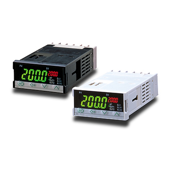
(10) Case color
N: Off-white
A: Off-black
2.2 Dimensions
(Unit : mm)
*1
Rubber (option)
For mounting of the SA200, panel thickness must be between 1 to 10 mm.
When mounting multiple SA200s close together, the panel strength should be checked to ensure proper support.
2.2 Dimensions
.
Fig.1
CAUTION
2
4 mm
Tighten each terminal screw to the specified torque found
in the manual to avoid electric shock, fire or malfunction.
For proper operation of this instrument, provide adequate
ventilation for heat dispensation.
Do not connect wires to unused terminals as this will
interfere with proper operation of the instrument.
Turn off the power supply before cleaning the instrument.
Do not use a volatile solvent such as paint thinner to clean
the instrument. Deformation or discoloration will occur. Use
a soft, dry cloth to remove stains from the instrument.
To avoid damage to instrument display, do not rub with an
abrasive material or push front panel with a hard object.
NOTICE
This manual assumes that the reader has a fundamental
knowledge of the principles of electricity, process control,
computer technology and communications.
The figures, diagrams and numeric values used in this
manual are only for purpose of illustration.
RKC is not responsible for any damage or injury that is
caused as a result of using this instrument, instrument
failure or indirect damage.
Periodic maintenance is required for safe and proper
operation of this instrument. Some components have a
limited service life, or characteristics that change over time.
(11) Output assignment code
No symbol: Standard output
03: PID action+ ALM1
[OUT1: Control output OUT2: ALM1 output
*1
04: PID action+ ALM1, ALM2
*1
[OUT1: Control output OUT2: AND output of ALM1 and ALM2
05: PID action+ ALM1, ALM2
*1
[OUT1: Control output OUT2: OR output of ALM1 and ALM2
06: PID action+ ALM1, ALM2
[OUT1: Control output OUT2: AND output of ALM1 and ALM2
07: PID action+ ALM1, ALM2 or ALM1 only
[OUT1: Control output OUT2: No output (The alarm state can be
checked via communication or by lamp lighting) ]
08: PID action+ ALM1, ALM2
[OUT1: Control output OUT2: Only for ALM1 output
(ALM2 can be checked via communication or by lamp lighting) ]
48
9.2
*
2
1
14.5
*
1
8.2
100
8
*2
Terminal cover (option)
When using the
mounting screws,
only turn one full
revolution after
the screw touches
the panel.
Fig.3
Fig.2
Fuse type: Time-lag fuse]
Always connect external wires starting from the
lower terminals (No.1 to 6). Disconnect the wires
starting from the upper terminals (No.7 to 12).
When multiple instruments are vertically closely
mounted, do not connect two or more solderless
terminal lugs to one terminal.
If multiple instruments are vertically
closely mounted, it is necessary to
bend the terminal lugs when they are
connected to the lower terminals.
Every effort has been made to ensure accuracy of all
information contained herein. RKC makes no warranty
expressed or implied, with respect to the accuracy of the
information. The information in this manual is subject to
change without prior notice.
No portion of this document may be reprinted, modified,
copied, transmitted, digitized, stored, processed or
retrieved through any mechanical, electronic, optical or
other means without prior written approval from RKC.
WARNING
: This mark indicates precautions that must be
CAUTION
: This mark indicates that if these precautions and
: This mark indicates that all precautions should be
!
: This mark indicates important information on
: This mark indicates supplemental information on
: This mark indicates where additional information
09: ALM1+ ALM2
[OUT1: ALM1 output
10: ALM1+ ALM2
*3
]
[OUT1: ALM1 output
11: ALM1+ ALM2
*4
]
[OUT1: ALM1 output
*3
*1
]
With hold action
*3
De-energized
*3
]
Accessories
Mounting brackets: 2
Mounting screws:
*4
Instruction Manual (IMR01D01-E1) : 1
Panel cutout
Individual mounting
Close horizontal mounting
+0.6
25
45
0
L1
L1 = 48 × n-3
n: number of units (2≤n≤6)
Weight 110 g
Close Mounting
Secure the mounting brackets in the positions as shown in Fig.4 and Fig.5.
Fig.4
• If the SA200s have waterproof/dustproof options, protection will
be compromised and not meet IP66 by close mounting.
• Two SA200s cannot be inserted into a panel cutout of 48×48 mm.
3.2 Terminal Configuration
Input terminals
Thermocouple (TC)
Voltage input
0 to 5 V DC , 0 to 10 V DC,
1 to 5 V DC
8
9
8
+
IN
TC
+
-
RTD
Current input
0 to 20 mA DC,
4 to 20 mA DC
7
8
9
8
A
B
B
RTD
+
Power supply terminals
1
2
1
2
AC
+
DC
−
L
N
100-
24 V
240 V
NO: Normally Open
OUT1 terminals
1
2
AC
L
N
Relay contact
Voltage pulse
24 V
3
OUT1
4
3
+
NO
Power supply voltage:
85 to 264 V AC (Power supply voltage range),
50/60 Hz, Rating: 100 to 240 V AC
21.6 to 26.4 V AC (Power supply voltage range),
50/60 Hz, Rating: 24 V AC
21.6 to 26.4 V DC (Power supply voltage range)
Rating: 24 V DC
Power consumption:
4 VA max.(at 100 V AC) 7 VA max.(at 240 V AC)
4 VA max.(at 24 V AC)
100 mA max.(at 24 V DC)
100 mA max.(at 24 V DC)
SYMBOLS
taken if there is danger of electric shock, fire, etc.,
which could result in loss of life or injury.
operating procedures are not taken, damage to
the instrument may result.
taken for safe usage.
installation, handling and operating procedures.
installation, handling and operating procedures.
may be located.
*4
*4
OUT2: ALM2 output
]
*4
*3
OUT2: ALM2 output
]
*3
*3
OUT2: ALM2 output
]
*2
LBA can be selected for only ALM1.
*4
Energized
2
Close vertical mounting
+0.6
0
+0.6
45
0
+0.3
L2 = 24 × n-1.8
0
n: number of units (2≤n≤6)
Fig.5
Option terminals
Communication
10
11
12
9
−
SG
T/R(A)
T/R(B)
RS-485
Contact input
10
11
12
9
NO
NO
−
DI1
DI2
7
8
9
10
11
12
1
2
3
4
5
6
OUT2 terminals
Relay contact
Voltage pulse
OUT1
4
5
OUT2
6
5
OUT2
6
−
+
−
12V
12V
NO
Outputs (OUT1,OUT2):
Relay contact output:
240 V AC, 2 A (Resistive load) 1a contact,
Electrical life 300,000 times or more (Rated load)
Voltage pulse output:
Input/output terminals are not isolated.
0/12 V DC (Load resistance 600 Ω or more)
Contact input (option):
Dry contact input
At open 500 kΩ or more
At close 10 Ω or less
Advertisement

Related Manuals for RKC INSTRUMENT SA200


Summary of Contents for RKC INSTRUMENT SA200
- Page 1 L2 = 24 × n-1.8 Excessive induction noise, static electricity, magnetic fields or noise. For mounting of the SA200, panel thickness must be between 1 to 10 mm. n: number of units (2≤n≤6) Direct air flow from an air conditioner.
-
Page 2: Error Displays
When AT is competed, the controller immediately changes to PID control. Underscale - PV is below ® RKC INSTRUMENT INC. Check the sensor or If the control system does not allow the AT cycling process, do not use AT the low input display range and set each PID constant to meet the needs of the application.
Need help?
Do you have a question about the SA200 and is the answer not in the manual?
Questions and answers