Advertisement
Advertisement

Related Manuals for La Gard 3000


Summary of Contents for La Gard 3000
- Page 1 ELECTRONIC ENTRY DEVICE INSTALLATION INSTRUCTIONS FOR BASIC AND GARD SERIES...
-
Page 2: Table Of Contents
TABLE OF CONTENTS GENERAL INFORMATION �������������������������������������������������������������������������������������������������������������������������������������������������������������������������� 1 ENTRY DEVICE MOUNTING TEMPLATES ������������������������������������������������������������������������������������������������������������������������������������������������ 3 3000 AND 3715 ENTRY DEVICE ���������������������������������������������������������������������������������������������������������������������������������������������������������������� 4 3035 & 3125 ROUND ENTRY DEVICE ������������������������������������������������������������������������������������������������������������������������������������������������������� 5 • Swingbolt instructions • Dead bolt instructions 3710 ANGULAR ENTRY DEVICE ��������������������������������������������������������������������������������������������������������������������������������������������������������������� 7 •... -
Page 3: General Information
ELECTRONIC ENTRY DEVICE Installation Instructions GENERAL INFORMATION In order to maintain the highest quality standards and ensure a problem-free application, please read this guide thoroughly before mounting the input unit. The installation instructions are the basis for Security Agency Approvals. The lock installation must be done in accordance to these instructions in order to maintain the labeled approval level. - Page 4 DIAL RING/FRONT HOUSING BASE MOUNTING TEMPLATE (P/N)762.128 Rev B EN 05/10 • © copyright 2009-2010 Kaba Mas LLC page 2...
-
Page 5: Entry Device Mounting Templates
8130 ENTRY DEVICES MOUNTING TEMPLATE DO NOT SCALE (P/N)762.128 Rev B EN 05/10 • © copyright 2009-2010 Kaba Mas LLC page 3... -
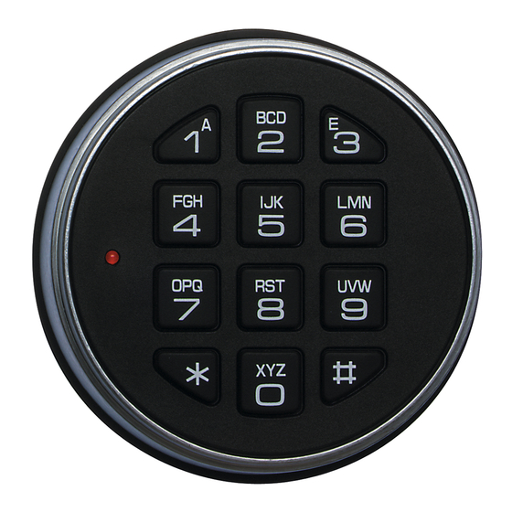
Page 6: 3000 And 3715 Entry Device
3000 AND 3715 ROUND ENTRY DEVICE The 3000 and 3715 Entry Device is designed with keyhole slots for ease of mounting and battery replacement. 1. Install the two #8-32 shoulder screws (US) or the M4-0.7 shoulder screws (metric) to mount the Entry Device to the door. -
Page 7: 3035 & 3125 Round Entry Device
3035 & 3125 ROUND ENTRY DEVICE 3035 & 3125 Entry Device SWING BOLT (Swingbolt Option) 1. Mount the dial plate (p/n 2676) centered on the through hole. Attach the dial plate with the two mounting screws US 8-32 (US) or the M4-0.7 (metric), and the shoulder bushings (p/n 2618). - Page 8 INSTALLING BATTERIES The 3035/3125 Entry Device required either a battery box (2788 or 4001), or a battery/alarm box (2789 or 4002) to provide power to the lock. Mount the battery box inside the safe, and connect the cable coming from the battery box directly into the connector port marked BAT on the lock.
-
Page 9: 3710 Angular Entry Device
3710 ANGULAR ENTRY DEVICE (ADDITIONAL INSTRUCTIONS 3716 ADAPTER) The 3710 Entry Device comes with the mylar portion of the keypad unattached. 1. Feed the key pad cable through the spindle cable hole from the front of the safe door. (Figure 5). 2. -
Page 10: 3750, 3750-K, 3750Ke, & 3190 Entry Device
3750, 3750-K, 3750KE, & 3190 ENTRY DEVICE SWING BOLT 1. Mount the dial plate (p/n 3752) centered on the through hole (Figure 6). Attach the dial plate with the two mounting screws US 8-32 (US) or the M4-0.7 (metric). 2. Slide the bearing plate (p/n 2674) over cable and press onto the fasteners on the Entry Device (Figure 7). - Page 11 DEAD BOLT/SPRING BOLT 1. Mount the dial plate (p/n 3752) centered on the through hole (Figure 6). Attach the dial plate with the two mounting screws US 8-32 (US) or the M4-0.7 (metric). . 2. Measure total mounting thickness (door thickness + mounting plate). (Figure 9.) 3.
- Page 12 Figure 13 In order to use either the Dead bolt or Spring bolt locks, with Entries 3000, 3710, 3715, and 8130 a method of retracting the bolt will be required. Knob Assembly (p/n 2666) is recommended. (P/N)762.128 Rev B EN 05/10 • © copyright 2009-2010...
-
Page 13: 2666 Knob Assembly
2666 KNOB ASSEMBLY 2666 The holes required to mount the knob need to be drilled 1.25" apart and must be centered over the spindle hole. 1. To install the Knob Assembly, remove the insert from the front of the knob. 2.
Need help?
Do you have a question about the 3000 and is the answer not in the manual?
Questions and answers