Table of Contents
Advertisement
Quick Links
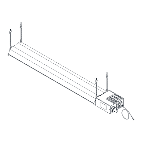
Series GR/ET Infrared Heater
Installation, Operation and Service Instructions
WARNING: If the information in these instructions are not followed
exactly, a fire or explosion may result causing property damage,
personal injury or loss of life.
Do not store or use gasoline or other flammable vapors and liquids in the
vicinity of this or any other appliance.
WHAT TO DO IF YOU SMELL GAS
Do not try to light any appliance.
Don't touch any electrical switch; do not use any telephone in your building.
Immediately call your gas supplier from a neighbor's phone. Follow the gas
supplier's instructions.
If you cannot reach your gas supplier, call the fire department.
Installation and service must be performed by a qualified installer, service
agency or the gas supplier.
Note: Not For Installation in Mobile Homes or Recreational Vehicle.
INSTALLER: Leave this manual with the appliance.
CONSUMER: Retain this manual for the future reference.
111 Progress Ave., New Castle, PA 16101
www.berner.com
02/14 LT094
Advertisement
Table of Contents
Troubleshooting

Subscribe to Our Youtube Channel
Related Manuals for Berner GR Series


Summary of Contents for Berner GR Series
- Page 1 Note: Not For Installation in Mobile Homes or Recreational Vehicle. INSTALLER: Leave this manual with the appliance. CONSUMER: Retain this manual for the future reference. 111 Progress Ave., New Castle, PA 16101 www.berner.com 02/14 LT094...
- Page 2 CAUTION: FIRE OR EXPLOSION HAZARD Maintain clearance to combustible constructions as further specified in this manual. Failure to do so could result in a serious fire hazard. Heaters should not be located in hazardous atmospheres containing flammable vapors or combustible dusts. Signs should be provided in storage areas specifying maximum safe stacking height.
-
Page 3: Table Of Contents
Table of Content Introduction ............................ 4 Installation Codes............................ 4 General Installation and Gas Codes ............................ 4 Aircraft Hangar Installation .............................. 4 Public Garage Installation .............................. 4 Parking Structures ................................ 4 Electrical .................................... 5 Venting .................................... 5 High Altitude .................................. 5 Safety Features .................................. 5 General Specifications ........................... 6 Gas Supply .............................. 6 Inlet Pressure .................................. 6 Manifold Pressure ................................. 6 Inlet Connection ................................... 6 Electric Supply .............................. 6 Heater Specifications ............................. 6 ... -
Page 4: Introduction
Introduction Superior Radiant Products is a company in the infrared heating industry founded on the principles of product quality and customer commitment. Quality commitments are evidenced by superior design, a regard for design detail and an upgrade of materials wherever justifiable. Customer commitment is apparent through our ready responses to market demands and a never ending training and service support program for and through our distributor network. -
Page 5: Electrical
Introduction The appliance must be isolated from the gas piping system by closing equipment shutoff valve during any pressure testing of the gas supply piping system at test pressures equal to or less than ½ psi (305 Kpa) Electrical All heaters must be electrically grounded in accordance with the National Electric Code, ANSI/NFPA 70 in the USA and the Canadian Electric Code, CSA C22.1 in Canada, and must comply with all local requirements. -
Page 6: General Specifications
General Specifications Gas Supply Inlet Pressure Natural Gas: Min. 5.0" W.C. Propane Gas: Min. 11.5" W.C. Max. 14.0" W.C. Max. 14.0" W.C. Manifold Pressure Natural Gas: 3.5" W.C. Propane Gas: 10.5" W.C. Inlet Connection Natural Gas or Propane Gas: 1/2" NPT. Female Electric Supply 120 VAC, 60 Hz., 1 Amp: Heater includes a 36"... -
Page 7: Clearance To Combustibles
Clearance to Combustibles Clearance to Combustible Materials. It is very important to observe the minimum clearance to combustibles at all times to avoid any possibility of property damage or personal injury. WARNING Clearances as marked on the heater body must be maintained from vehicles parked beneath. Signs should be posted identifying any possible violation of the clearance distances from the heater in all vehicle areas. - Page 8 Clearance to Combustibles Configuration Dimension 30,000 BTUh 45,000 BTUh 2˝ 2˝ 18˝ 18˝ Standard 36˝ 50˝ 18˝ 18˝ 2˝ 3˝ 2˝ 3˝ 45° Tilt 33˝ 48˝ 33˝ 48˝ 5” 5” Vented Table 1: Clearance to Combustible Table 45° Figure 2: Clearance to Combustible Diagram CAUTION In all cases, the minimum hanging height from the floor shall be: In Canada: 7' feet...
-
Page 9: Installation Detail
Installation Detail Installation Sequence The heater is sent with all parts necessary for installation with the exception of chain. It is recommended that the heater be hung as high as possible and along an uncluttered wall to give the reflector a widest possible “view” of the space to be heated. Avoid installation directly over vehicle parking, over cabinets, or where an open door will interfere. -
Page 10: Outdoor Installation
Installation Detail Outdoor Installation For outdoor installations the heater must be installed not more than 8" from beneath awnings, and not less than 24" from back and side as shown in Figure 4. If the heater cannot be protected from the elements by an overhang, then a protective cover must be installed as shown in Figure 7, Figure 8 and Figure 9. - Page 11 Installation Detail 8.39" or ("B/3") Max. 24.00" Min. or ("B") Figure 5: Mounting Distances for Outdoor Installations under Eaves. 8.00" Max. or ("B/3") 8.00" Max. or ("B/3") 28.00" Min. or ("B") 28.00" Min. or ("B") Figure 6: Mounting Distances for Tilted (45°) Outdoor Installations under Eaves. In the case where the heater is installed at a 45°...
- Page 12 Installation Detail When a heater is installed outdoors without the presence of an adequate eave, then a protective cover must be installed as illustrated below. This cover is available from your local dealer (Part # RS020). Cover Installation Sequence Install support brackets on to heater covers as shown in step 1 in Figure 7. ...
- Page 13 Installation Detail Note: Close all open ended "S" hooks, chain links, and turnbuckles or any open connection. Extension Cover Figure 9: Extension Cover for 45° Outdoor Installations Series GR Page 13 February 10, 2014...
-
Page 14: Venting / Combustion Air Ducting
Venting / Combustion Air Ducting General Requirements Refer to the National Fuel Gas Code, ANSI Z223.1 (NFPA 54) in the USA and CAN/CGA B149.1 and B149.2 Installation Codes in Canada, as well as all local requirements for vertical venting and general guidance for minimum distances to openings to the building. - Page 15 Venting / Combustion Air Ducting 7" 7" Figure 11: Minimum Clearance under an Eave The 2"-inch flue vent is inside (concentric with) the 4" inch combustion air inlet duct. Each of the former must be seamless and all joints must be fastened with screws and sealed with GE RTV-106 high temperature sealant (or equivalent) refer to Figure 12.
-
Page 16: Optional" Horizontal Elbow Vent Terminal
Venting / Combustion Air Ducting Optional Horizontal Elbow Vent Terminal The GR Models are approved to be used with an Elbow as a Horizontal Vent Terminal see Figure 13 for installation details.. Wall Terminal P/N RS006 Ø2" Flue Pipe "Optional" Horizontal Elbow Vent Terminal Seal Joint with RTV Silicone... -
Page 17: Roof Venting
Venting / Combustion Air Ducting Roof Venting When heater is to be vented through a roof (Vertical Venting), a B-Vent adapter kit (Part # RS022) must be used. The B-vent must be installed in accordance to the National Fuel Gas Code, ANSI Z223.1 (NFPA 54) in the USA and CAN/CGA B149.1 and B149.2 Installation Codes in Canada. -
Page 18: Gas Piping
Gas Piping General Requirements The gas meter and service must be sufficiently large to supply gas to the connected building gas load including the heating equipment and any other gas-fired equipment. Additionally, the gas distribution piping must be designed according to local and national ordinances. Generally (low pressure) systems designed with a maximum 1/2"-inch W.C. -
Page 19: Electrical Wiring
Electrical Wiring General Requirements Heaters are normally controlled with the thermostat that is included with your equipment. A 24V signal is supplied by the heater control module for thermostat connection. Refer to wiring diagram, Figure 16. A bulkhead fitting in the back panel of the control box is provided for the appropriate wire. In all cases, heaters must be grounded in accordance with the National Electric Code, ANSI/NFPA 70 in the USA, and the Canadian Electric Code, CSA C22.1 in Canada, and must comply with all local requirements. -
Page 20: Operation / Maintenance
Operation / Maintenance Starting Sequence of Operation Turn the thermostat up. When the thermostat calls for heat, the blower motor will energize. When the motor approaches nominal running RPM, the air-proving switch closes and activates the ignition module. ... -
Page 21: Trouble Shooting
Trouble Shooting Blower Motor Fails to Run Is the thermostat calling for heat? Is there 115V at the burner receptacle? Check blower side door for seal. Repair as necessary. Check blower for obstructions. Replace blower if necessary. No Gas Supply ... -
Page 22: Troubleshooting Chart
Trouble Shooting Troubleshooting Chart Series GR Page 22 February 10, 2014... -
Page 23: Replacement Parts
Replacement Parts Figure 17: Replacement Parts ITEM # PART # DESCRIPTION ITEM # PART # DESCRIPTION Blower Motor CE010 Power Cord CE011 Sight Glass Assy CE158 CH011 45,000 BTU Pressure Switch 30,000 BTU Pressure Switch CE003 CE160 Flame Sensor RE019 Ignitor CG001 Gas Valve - Natural - Honeywell... -
Page 24: Warranty
AND EXCLUSIVE REMEDIES. NO OTHER EXPRESS OR IMPLIED WARRANTIES ARE MADE INCLUDING, BUT NOT LIMITED TO, ANY IMPLIED WARRANTY OF MERCHANT ABILITY OR FITNESS FOR A PARTICULAR USE OR PURPOSE. Address questions to your local distributor/ or Berner International Corp. 111 Progress Ave., New Castle, PA 16101 1-800-343-7991 Heater Series...
Need help?
Do you have a question about the GR Series and is the answer not in the manual?
Questions and answers