Table of Contents
Advertisement
Quick Links
Advertisement
Table of Contents

Related Manuals for Sierra Wireless MP 555


Summary of Contents for Sierra Wireless MP 555
- Page 1 MP 555 GPS Rugged Wireless Modem Vehicle Installation Guide 2130297 Rev 2.1...
- Page 3 (i.e., have errors) or be totally lost. Although significant delays or losses of data are rare when wireless devices such as the Sierra Wireless modem are used in a normal manner with a well-constructed network, the Sierra Wireless modem should not be used in situations where...
- Page 4 Notwithstanding the foregoing, in no event shall Sierra Wireless, Inc. and/or its affiliates aggregate liability arising under or in connection with the Sierra Wireless, Inc. product, regardless of the number of events, occurrences, or claims giving rise to liability, be in excess of the price paid by the purchaser for the Sierra Wireless, Inc.
-
Page 5: Contact Information
Trademarks “Heart of the Wireless Machine” is a registered trademarks of Sierra Wireless, Inc. Sierra Wireless, the Sierra Wireless logo, the red wave design, and Watcher are trademarks of Sierra Wireless, Inc. ® Windows is a registered trademark of Microsoft Corporation. - Page 6 MP 555 GPS Vehicle Installation Guide 2130297...
-
Page 7: Table Of Contents
Introducing the MP 555 GPS modem ........9... - Page 8 MP 555 GPS Vehicle Installation Guide Power Wiring ........... . . 20 The Power Connector .
-
Page 9: Introducing The Mp 555 Gps Modem
The network connection provided by the MP 555 GPS can be used to access shared data, browse the Internet, and send and receive e-mail and text messages. The modem also allows for... -
Page 10: System Requirements
MP 555 GPS Vehicle Installation Guide System Requirements Supported Platforms The MP 555 GPS wireless modem connects to a personal Note: Do not connect the computer with either a serial cable or USB cable. Your MP 555 GPS to a USB port on a computer must therefore have either an available serial port or PC before installing the software. -
Page 11: Package Contents
Sierra Wireless to obtain them. Documentation The MP 555 GPS documentation consists of two guides and an online help system. MP 555 GPS Modem Vehicle Installation Guide (this document) provides instructions on installing the hardware, describing how to: •... -
Page 12: Modem Accessories
<F1> key. Modem Accessories For information about accessories for the MP 555 GPS wireless modem—including cables and antennas—contact your account manager at your reseller or at Sierra Wireless. Warranty Sierra Wireless, Inc. -
Page 13: Installing The Mp 555 Gps Modem In A Vehicle
Completing the Installation Note: The MP 555 GPS is Figure 2-1: Basic diagram for the installation of the MP 555 GPS in a vehicle designed for negative-ground equipped with a notebook PC and a combination antenna, using the car vehicles only. It will not function battery for power and ignition-sense w ng for power on/off. -
Page 14: Gps And I/O Options
(Global Positioning System) and for attaching input/output devices. GPS. If you plan to use the MP 555 GPS’s built-in GPS module, you must connect a GPS antenna and an antenna cable, or use a combination antenna that can connect to both the GPS and CDMA RF connectors on the MP 555 GPS housing. -
Page 15: Connector Panel
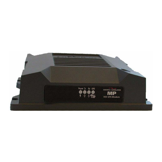
I/O connector (female DB15) CDMA RF antenna Ground screw (femal e TNC) Figure 2-3: The connector panel of the MP 555 GPS modem. Indicator Panel The MP 555 GPS’s indicator panel includes four indicator lights: Power Receive (Rx) Transmit (Tx) Figure 2-4: The indicator panel of the MP 555 GPS modem. -
Page 16: Required Equipment
I/O device is being installed. (See “I/O Port Connections” on page 25.) Mounting the Modem The MP 555 GPS can be mounted in the trunk of the vehicle, Note: The MP 555 GPS modem, under the dashboard, or under a front or rear seat. -
Page 17: Mounting Procedure
Use the supplied mounting screws and washers to secure the MP 555 GPS through the holes along the edge of the case bottom. Figure 2-6: The bottom of the MP 555 GPS housing. Arrows indicate the mounting holes. Rev 2.1 Jan.05... -
Page 18: Grounding The Modem
MP200 harness has a fused ground wire The power harness for the MP 555 GPS modem has 5 A fuses whil e the MP 555 GPS harness on the red power wire and the white ignition sense wire, but has an unfused ground wire. -
Page 19: Antennas
· A dual-band antenna that supports both frequencies can be used. If your MP 555 GPS will only be connected to net works that use one of the bands, an appropriate single- band antenna is sufficient. Contact your service provider for information about radio bands used in your area. -
Page 20: Antenna Locations
SMA connector (for the GPS antenna). Hand-tighten the connectors; do not use tools. Power Wiring In a typical installation, the MP 555 GPS is connected to the Note: To avoid RF nterference vehicle’s battery with the supplied power harness (or if an... -
Page 21: Power Connector (Molex) Pinouts
Installing the MP 555 GPS Modem in a Vehicle Power connector (Molex) pinouts The pinouts for the Molex connector on the power harness are as follows: Note: If you are install ng an MP 555 GPS in a vehicle in... -
Page 22: Ignition Sense Options
MP 555 GPS to be turned on or off regardless of the sense wire, not the red battery position of the ignition key. In this configuration, the... -
Page 23: Making Proper Power Connections
Powering On the Modem Once the MP 555 GPS modem is powered on, the Power and GPS indicators on the indicator panel should light, either solid-on or flashing. -
Page 24: Cable Connection To The Computer
MP 555 GPS Vehicle Installation Guide Cable Connection to the Computer The MP 555 GPS connects to a PC using a standard serial cable Note: Do not connect the (with a DB9 connector on the modem end) or USB cable (with... -
Page 25: Connecting The Serial Or Usb Cable
7. Analog input 2 (AIN2) Figure 2-13: Pinouts for a male DB15 I/O cable (left) that connects to the MP 555 GPS’s female DB15 I/O connector (right). Note that the two figures’ pinouts are mirror images of one another, since they plug together. -
Page 26: Completing The Installation
MP 555 GPS Vehicle Installation Guide Completing the Installation Once you have mounted the MP 555 GPS and connected all the appropriate cables and antennas, you can power on the computer and the modem. When you install and configure the supplied software from the... -
Page 27: Technical Specifications
There are four green LEDs (Light Emitting Diodes) on the front • I/O Port panel of the MP 555 GPS. When the MP 555 GPS is first Characteristics powered (and when the modem is reset), all four LEDs should flash briefly. The table below shows the behavior of the LEDs during modem operation. -
Page 28: Rf And Electrical Specifications
MP 555 GPS Vehicle Installation Guide RF and Electrical Specifications Table 3-2: Radio frequency & electrical specifications Approvals Industry Canada Compliance Compliant with: IS-95A, IS-98D, IS-707A, IS707A-1, CDMA Developers Group Voltage Range 9 - 36 VDC Current Max transmit (23 dBm output) -
Page 29: Environmental Specifications
Technical Specifications Environmental Specifications Table 3-3: Environmental specifications Operating -30 to +70 °C temperature (-22 to +158 °F) Storage -40 to +85 °C temperature (-40 to +185 °F) Humidity 95% RH non-condensing SAE J1455 4.2 MIL 202G 103B and 106G MIL 810F 507.4 Vibration SAE J1455 4.9... -
Page 30: Gps Performance
MP 555 GPS Vehicle Installation Guide GPS Performance Table 3-5: GPS performance Accuracy Horizontal: < 6 m (50%), < 9 m (90%) Altitude: < 11 m (50%), < 18 m (90%) Velocity: 0.06 m/sec Acquisition times Re-acquisition < 2 sec (90%) Hot start: <... -
Page 31: Regulatory Information
Approval Industry Canada Approval • FCC Approval (U.S.A.) To ensure that the MP 555 GPS modem meets the Health Note: Unauthorized mod fica- Canada’s Safety Code 6 requirements, a separation distance of tions or changes not expressly at least 20 cm must be maintained between the modem’s... - Page 32 MP 555 GPS Vehicle Installation Guide 2130297...
- Page 33 Index analog sensor, LED, 15 antenna, 19 operation, antenna connector, audio connector, 15 Mounting, mounting, 16– 18 CDMA antenna, 19 MP200 modem connectors, 15 power harness, 18 crimp terminals, replacing, 17, current, on/off switch, DB15 operating systems supported, connector, 15 output power, pinouts, 25 connector, 15...
- Page 34 MP 555 GPS Vehicle Installation Guide USB connector, technical specifications, 27– 30 TNC connector, 15 transmit frequencies, voltage range, 28 Tx indicator, 15, 27 voltage specifications (serial cable), USB cable warranty, 12 installing, 24 wire splicing, maximum length, 16 supported operating systems,...
Need help?
Do you have a question about the MP 555 and is the answer not in the manual?
Questions and answers