Table of Contents
Advertisement
Quick Links
Advertisement
Table of Contents
Troubleshooting

Related Manuals for Rheem ARL-JEZ 16 Seer Series


Summary of Contents for Rheem ARL-JEZ 16 Seer Series
-
Page 1: Installation Instructions
INSTALLATION INSTRUCTIONS AIR-COOLED CONDENSING UNITS (-)ARL-JEZ 16 SEER AND (-)ASL-JEZ 18 SEER MODELS EQUIPPED WITH THE INTEGRATED COMFORT CONTROL SYSTEM™ Featuring Industry Standard R-410A Refrigerant ISO 9001:2008 92-101691-02-10 [ ] INDICATES METRIC CONVERSIONS SUPERSEDES 92-101691-02-09... -
Page 2: Table Of Contents
T BLE OF CONTENTS Checking Product Received ........2 Dimensions . -
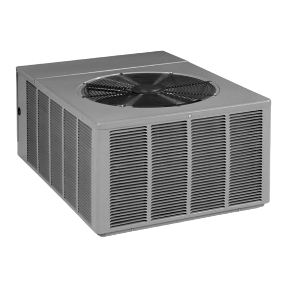
Page 3: Dimensions
FIGURE 1 UNIT MODEL NUMBER EXPLANATION DIMENSIONS AND INSTALLATION CLEARANCES (-)ARL – 036 J E Z IR DISCH RGE Z - SCROLL COMPRESSOR AIR DISCHARGE ALLOW 600 [1524 mm] CLEARANCE LLOW 60" [1524 mm] CLE R NCE E = EQUIPPED WITH THE COMFORT CONTROL SYSTEM™... -
Page 4: Electrical & Physical Data
ELECTRICAL & PHYSICAL DATA TABLE 1 (-)ARL-JEZ ELECTRICAL DATA ELECTRIC L PHYSIC L Outdoor Coil Weight Compressor Phase Fuse or H CR Model Minimum Refrig. Frequency Motor Circuit Breaker Number Locked Circuit Rated Load (Hz) Full Load R RL- Rotor Face rea Shipping mpacity... -
Page 5: Corrosive Environment
CORROSIVE ENVIRONMENT The metal parts of this unit may be subject to rust or deterioration if exposed to a corrosive environment. This oxidation could shorten the equipment’s useful life. Corrosive elements include, but are not limited to, salt spray, fog or mist in seacoast areas, sulphur or chlorine from lawn watering systems, and various chemical conta- minants from industries such as paper mills and petroleum refineries. -
Page 6: Unit Mounting
• Refer to clearance recommendations on Page 3. o 24” to the service panel access o 60” above condenser fan discharge (unit top) to prevent recirculation o 12” to condenser coil grille air inlets (per condenser). FOR CONDENSERS WITH SP CE LIMIT TIONS In the event that a space limitation exists, we will permit the following clearances: Single Unit Applications: One condenser inlet air grille side may be reduced to no less than an 8-inch clearance. -
Page 7: Refrigerant Connections
REFRIGER NT CONNECTIONS All units are factory charged with Refrigerant R-410A. All models are supplied with service valves. Keep tube ends sealed until connection is to be made to prevent system contamination. TOOLS REQUIRED FOR INST LLING & SERVICING R-410 MODELS Manifold Sets: -Up to 800 PSIG High side -Up to 250 PSIG Low Side... -
Page 8: Specification Of R-410A
SPECIFIC TION OF R-410 : Application: R-410A is not a drop-in replacement for R-22; equipment designs must accommodate its higher pressures. It cannot be retrofitted into R-22 condens- ing units. Pressure: The pressure of R-410A is approximately 60% (1.6 times) greater than R-22. -
Page 9: Interconnecting Tubing
The thermostatic expansion valve is specifically designed to operate with R-410A. DO NOT use an R-22 TXV or evaporator. The existing evaporator must be replaced with the factory specified TXV evaporator specifically designed for R-410A. LOC TION Do not install the indoor evaporator coil in the return duct system of a gas or oil fur- nace. - Page 10 TUBING INST LL TION Observe the following when installing correctly sized type “L” refrigerant tubing between the condensing unit and evaporator coil: • If a portion of the liquid line passes through a hot area where liquid refrigerant can be heated to form vapor, insulating the liquid line is required. •...
- Page 11 TABLE 2 SUCTION LINE LENGTH SIZE VS. CAPACITY MULTIPLIER (2-STAGE R-410A) Unit Size 2 Ton 3 Ton 4 Ton 5 Ton Suction Line Connection 3/4" I.D. 3/4" I.D. 7/8" I.D. 7/8" I.D. Size — Suction Line 5/8* 3/4* 7/8* 7/8* Run Feet —...
-
Page 12: Liquid Line Size
TABLE 4 LIQUID LINE SIZING (2-STAGE R-410A) LIQUID LINE SIZE - OUTDOOR UNIT ABOVE INDOOR COIL Liquid Line Size R-410A Liquid Line Outdoor unit Above Indoor Coil (Cooling Only - Does not apply to Heat Pumps) System Connection Line Size (Inch Total Equivalent Length - Feet [m] Capacity Size... -
Page 13: Suction Line Size
TABLE 5 (-)ARL SUCTION LINE SIZING SUCTION LINE SIZE - OUTDOOR UNIT ABOVE INDOOR COIL Suction Line Size R-410A Line Size Line Size System Connection (Inch O.D.) Outdoor Unit ABOVE Indoor Coil (Cooling Only - Does not apply to Heat Pumps) Capacity Size (Inch [mm]... -
Page 14: Evacuation Procedure
EV CU TION PROCEDURE Evacuation is the most important part of the entire service procedure. The life and efficiency of the equipment is dependent upon the thoroughness exercised by the serviceman when evacuating air and moisture from the system. Air or nitrogen in the system causes high condensing temperatures and pressure, resulting in increased power input and non-verifiable performance. -
Page 15: Checking Refrigerant Charge
air back to the blower. If they are too small, they also cause noise. The installers should balance the air distribution system to ensure proper quiet airflow to all rooms in the home. This ensures a comfortable living space. These simple mathematical formulas can be used to determine the CFM in a resi- dential or light commercial system. - Page 16 Addition of R-410A will raise high-side pressures (liquid, and discharge). NOTICE System maintenance is to be performed by a qualified and certified technician. All steps listed should be performed to insure proper charge has been set. For mea- suring pressures, the service valve port on the liquid valve (small valve) and the service port on the suction line between the reversing valve and compressor are to be used.
- Page 17 necessary. CHARGING BY LIQUID SUB-COOLING MUST BE USED FOR FINAL CHARGE ADJUSTMENT. Turn the power on to the furnace or air handler. Start the outdoor unit and the fur - nace or air handler with the thermostat. Verify that the outdoor unit is operating in second stage and the indoor air mover is delivering the second-stage airflow for the system size.
- Page 18 Step 2. Note the measured Liquid Pressure, Pliq = ______psig, as measured from the liquid (small) service valve. Use the pressure temperature chart below to note the corresponding saturation temperature for R410A at the measured liquid pressure. Liquid Saturation Temperature, SAT°F= _________°F. TABLE 6 SATURATION R-410A...
-
Page 19: Electrical Wiring
TABLE 7 Suction System Problem Discharge Pressure Sub-cooling Compressor Amps Pressure Low/ Overcharge * High High High Normal Undercharge Liquid Line Restriction ** High Low Evaporator Airflow High High/ Dirty outdoor Coil High High Normal Low Outside Ambient temperature High TXV sensing bulb charge lost High Poorly Insulated Sensing Bulb... -
Page 20: Factory Installed Accessories
FIGURE 2 IF M XIMUM OUTLET TEMPER TURE RISE IS DESIRED, IT IS RECOMMENDED TH T CONTROL WIRING FOR GAS OR OIL FURNACE W1 (W/BK) ND W2 (W/BL) BE JUMPERED TOGETHER. TYPIC L THERMOST T TYPIC L THERMOST T SUBB SE FOR TYPICAL GAS OR OIL HEAT FOR TYPICAL ELECTRIC HEAT SUBB SE... -
Page 21: Field Installed Accessories
FIELD INST LLED CCESSORIES COMPRESSOR CR NKC SE HE T (CCH) While scroll compressors usually do not require crankcase heaters, there are instances when a heater should be added. Refrigerant migration during the off cycle can result in a noisy start up. Add a crankcase heater to minimize refrigeration migration, and to help eliminate any start up noise or bearing “wash out.”... - Page 22 FIGURE 3 LOW PRESSURE CONTROL INPUT COMPRESSOR O.D. FAN (OFM) RELAY SOLENOID ICC BOARD HIGH PRESSURE CONTROL INPUT OUTPUT TEST BUTTON RED LED (Y1) FIELD LINE VOLTAGE LOW VOLT FUSE CONNECTION (ST1) THERMOSTAT CONNECTION (E2) COMPRESSOR WIRING SW2 BUTTON CONNECTOR (ST2) AMBIENT SENSOR ICC (INTEGRATED COMPRESSOR...
- Page 23 • Y2 – Call for unit second stage operation (cooling) Low Volt Fuse • If required replace with 3 A automotive ATC style blade fuse Low Pressure Control (LPC Input – E14) • Low-pressure control is factory installed • Low pressure control is an automatic resetting device High Pressure Control (HPC Input –...
-
Page 24: Status And Diagnostic Description
Status and Diagnostic Description 7 -Segment Diagnostic Description Status / Possible Cause -Troubleshooting Display Information Code Standby Standby - No call for operation First Stage or Single Stage Unit Operation Second stage unit operation (2-stage unit only) Anti-Short Cycle Timer (3 minutes) or Waiting for anti-short cycle timer to expire c or Minimum Run Timer (30 seconds) -
Page 25: Service
5 (*) (***) Compressor will not run 1. Check for damaged, miswired, or wrong run Active Protection – After detecting compressor capacitor will not run the ICC control will shut the unit 2. Check for damaged or miswired start capacitor down. -
Page 26: General Service Analyzer Charts
GENER L SERVICE N LYZER CH RTS COMPRESSOR OVERHEATING SYMPTOMS POSSIBLE CAUSE CHECK/REMEDIES High superheat Low charge Check system charge Faulty metering device Restricted cap tube, TEV (TXV) Power element superheat adjustment Foreign matter stopping flow High internal load Hot air (attic) entering return Heat source on;... - Page 27 SYMPTOMS POSSIBLE CAUSE CHECK OR REMEDIES Short cycling of compressor (cont.) Low charge Check system charge Low evaporator air flow Dirty coil Dirty filter Duct too small or restricted Faulty run capacitor Replace Faulty internal overload Replace compressor ELECTRICAL (See Control Diagnostics) SYMPTOMS POSSIBLE CAUSE CHECK OR REMEDIES...
- Page 28 LOSS OF LUBRICATION SYMPTOMS POSSIBLE CAUSE CHECK OR REMEDIES Compressor failures Line tubing too long Add oil to the recommended level Line tubing too large Reduce pipe size to improve oil return Low suction pressure Low charge Check system charge Refrigerant leaks Repair and recharge Cold, Noisy compressor - Slugging...
- Page 29 THERMOSTATIC EXPANSION VALVES SYMPTOMS POSSIBLE CAUSE CHECK OR REMEDIES High Superheat, Low Suction Pressure Moisture freezing and blocking valve Recover charge, install filter-drier, evacuate system, recharge Dirt or foreign material blocking valve Recover charge, install filter-drier, evacuate system, recharge Low refrigerant charge Correct the charge Vapor bubbles in liquid line Remove restriction in liquid line...
- Page 30 THERMOSTATIC EXPANSION VALVES SYMPTOMS POSSIBLE CAUSE CHECK OR REMEDIES Superheat is low to normal Unequal evaporator circuit loading Ensure air flow is equally distributed with low suction pressure through evaporator Check for blocked distributor tubes Low load or airflow entering Ensure blower is moving proper air evaporator coil Remove/Correct any air flow...
- Page 31 FIGURE 4 E-SERIES DIAGNOSTIC LABEL C aution – UNI T M A Y ST A R T SUDDE NL Y A ND W I T H OUT W A R NI NG Solid red L E D light indicates a thermostat call for unit operation is present at the ICC. ICC will attempt to start unit after short cycle timer expires or when in Active Protection mode will attempt to restart unit prior to L ockout mode.
-
Page 32: Trouble Shooting
TROUBLE SHOOTING In diagnosing common faults in the air conditioning system, it is useful to present the logical pattern of thought that is used by experienced technicians. The charts which follow are not intended to be an answer to all problems, but only to guide your thinking as you attempt to decide on your course of action. - Page 33 MECHANICAL CHECKS FLOW CHART Unit Running? Pressure problems? Go to Electrical Checks Flow Chart High Head Pressure Low Head Pressure Low Suction Pressure Dirty Condenser Coil Low on Charge Dirty Filters Inoperative Outdoor Fan Open IPR Valve Dirty Evaporator Overcharge Low Ambient Temperature Inadequate Airflow Recirculation of...
-
Page 34: System Charge Troubleshooting
SYSTEM CH RGE TROUBLESHOOTING TABLE 9 TEMPERATURE PRESSURE CHART SUPERHE T C LCUL TION TEMP R-410A (Deg. F) PSIG 1. Measure the suction pressure at the suction line service valve. -150 — 2. Convert the suction pressure to saturated temperature. See Table 9. -140 —... -
Page 35: Trouble Shooting Chart
How do I know if the low voltage solenoid is switching? Go through the four standard troubleshooting steps. If inconclusive do the following: 1. Make sure the compressor is OFF. 2. Apply 18 to 28V AC to the solenoid pins at the pump. 3. -
Page 36: Wiring Diagrams
FIGURE 5 (-)ARL-025, -038, -049 WIRING DIAGRAM... - Page 37 FIGURE 6 (-)ARL-061 JEZ, (-)ASL-024 JEC, (-)ASL-025 JEZ, (-)ASL-036 JEC, (-)ASL-037JEZ WIRING DIAGRAM...
Need help?
Do you have a question about the ARL-JEZ 16 Seer Series and is the answer not in the manual?
Questions and answers
what size condensor does this unit have to be replaced
To replace a Rheem ARL-JEZ 16 SEER Series unit, you need to match the nominal capacity. Based on the model number explanation, the sizes are:
- 024/025 = 24,000 BTU/hr (2 tons)
- 036/037/038 = 36,000 BTU/hr (3 tons)
- 048/049 = 48,000 BTU/hr (4 tons)
Therefore, the size of the replacement condenser must match the BTU/hr rating indicated in the model number of the existing unit. For example, if the current unit is ARL–036, you need a 36,000 BTU/hr (3-ton) condenser.
This answer is automatically generated