Table of Contents
Advertisement
Advertisement
Table of Contents

Related Manuals for Inter-m V2-1000


Summary of Contents for Inter-m V2-1000
- Page 1 Operation anual Professional Power mplifier 2-1000/2000/3000/4000...
- Page 2 Welcome personal welcome to you from the management and employees of Inter-M ll of the co-workers here at Inter-M are dedicated to providing excellent products with inherently good value, and we are delighted you have purchased one of our products.
-
Page 3: Table Of Contents
Stereo Installation ..........................9 Parallel Installation ..........................9 Bridge Mono Installation ........................10 Linked Installation..........................10 Connections ..........................11 Stereo/Parallel Connection ......................12 Bridge Mono Connection .......................12 Block Diagram ..........................13 Specifications ..........................14 Service Procedures............................16 Schematic .............................16 Parts List ............................16 Variations and Options .......................16 Warranty ............................16 V2-1000/2000/3000/4000... -
Page 4: Unpacking
8. The product is ready for operation. Slowly increase the level control to the desired operating level. void illuminating the clip indicator and do not apply too much power to the speakers. 9. Operate the product and the system in a manner which does not illuminate the clip warning indicator. V2-1000/2000/3000/4000... -
Page 5: Installation
S3125A S3125A V2-1000/2000/3000/4000... -
Page 6: Description
PROFESSION L POWER MPLIFIER Description Description - V2-1000 2U rack space, 2 channel amplifier capable of 1150W into 4 load(bridged mono). - V2-2000 2U rack space, 2 channel amplifier capable of 1850W into 4 load(bridged mono). - V2-3000 2U rack space, 2 channel amplifier capable of 3300W into 4 load(bridged mono). -
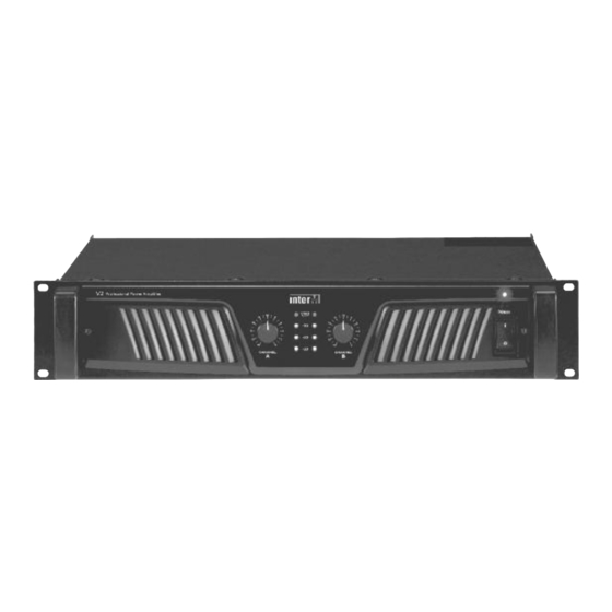
Page 7: Front Panel
This confirms the amplifier is switched on and receiving C mains power when illuminated. When switched on, the indicator is illuminated dimly for stand-by and then fully illuminated with prot/clip indicator for mute status, after that, only this illuminated fully activating the amplifier. V2-1000/2000/3000/4000... - Page 8 You can switch on after abnormal situation released and then the amplifier will be recovered. mplifiers are always the last item in a system to be turned on. It is generally a good idea to reduce the level controls before applying C mains power. V2-1000/2000/3000/4000...
-
Page 9: Rear Panel
4. VOLT GE G IN SELECTOR SWITCH You can drive the amplifier with different gain structure, 1V, 32dB or 26dB, which is possible the amplifier to accept a various input level. (V2-1000/2000 Voltage Gain: 1V, 26dB, 20dB) 5. B L NCED TRS INPUT CONNECTORS Each input channel is equipped with a TRS connector. - Page 10 The 30Hz position reduces the signal amplitude below 30Hz to conserve power and help protect the loudspeakers. The 50Hz position reduces the signal amplitude below 50Hz to conserve power and help protect the loudspeakers. V2-1000/2000/3000/4000...
-
Page 11: Stereo Installation
PROFESSION L POWER MPLIFIER pplications pplications pplications pplications Stereo Installation Parallel Installation V2-1000/2000/3000/4000... -
Page 12: Bridge Mono Installation
PROFESSION L POWER MPLIFIER pplications pplications Bridged Mono Installation Linked Installation In V2-Series, Linking is possible when in Stereo/Parallel or Bridged Mono operation. V2-1000/2000/3000/4000... -
Page 13: Connections
PROFESSION L POWER MPLIFIER pplications pplications Connections Inter-M products are wired according to professionally accepted wiring practices used throughout the world. 1. XLR INPUTS Balanced XLR connectors are wired as described: Pin #1 Shield Pin #2 Positive Pin #3 Negative XLR M LE 2. -
Page 14: Stereo/Parallel Connection
Bridged Mono operation has a minimum load impedance of 4 . Stereo/Parallel Connection Wiring Using Both Speaker Connectors Wiring Two Speakers to the Channel Speaker Connector Bridge Mono Connection Wiring a Speaker in Bridged Mono to the Channel Speaker Connector V2-1000/2000/3000/4000... -
Page 15: Block Diagram
PROFESSION L POWER MPLIFIER Block Diagrams Block Diagram V2-1000/2000 V2-3000/4000 V2-1000/2000/3000/4000... -
Page 16: Specifications
PROFESSION L POWER MPLIFIER Specifications Specifications 0dB=1V V2-1000 V2-2000 V2-3000 V2-4000 120V C 230V C 120V C 230V C 120V C 230V C 120V C 230V C Continuous verage Output Power Per Channel Stereo Mode 8 (T.H.D 0.1%) 190W 180W... - Page 17 PROFESSION L POWER MPLIFIER Specifications Specifications (U.K/ ustralia Version) 0dB=1V V2-1000 V2-2000 V2-3000 V2-4000 240V C 240V C 240V C 240V C Continuous verage Output Power Per Channel Stereo Mode 8 (T.H.D 0.1%) 170W 280W 500W 650W (1kHz, Both Channels Driven) 4 (T.H.D 0.1%)
-
Page 18: Service
To obtain specific warranty information and available service locations contact Inter-M directly or the authorized Inter-M Distributor for your specific country or region. - Page 19 V2-1000/2000/3000/4000...
- Page 20 Inter-M, Ltd. (Korea) began operations in 1983. Since then, Inter-M has grown to become one of the largest manufacturers of professional audio and commercial sound electronics equipment in the world. Inter-M has gained worldwide recognition for its own branded products, as well as private label manufacturing of electronics sold under other names (OEM).
Need help?
Do you have a question about the V2-1000 and is the answer not in the manual?
Questions and answers