
Related Manuals for Electrolux EW30DF65GB


Summary of Contents for Electrolux EW30DF65GB
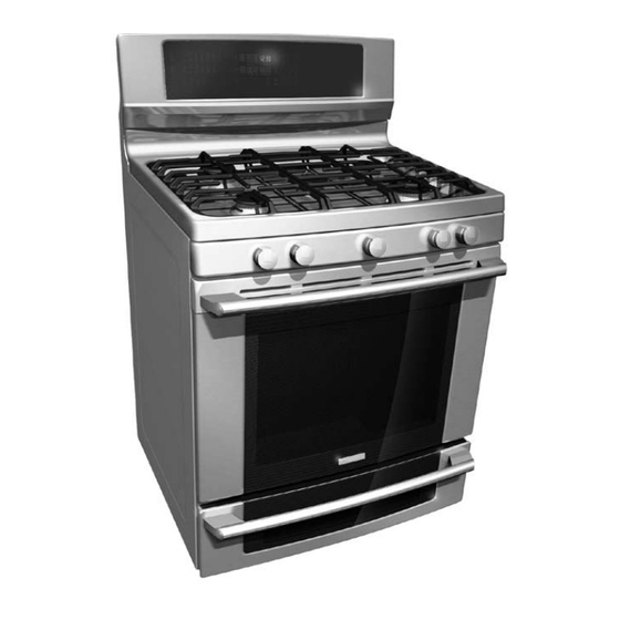
- Page 1 FREESTANDING DUAL FUEL RANGE PRODUCT SERVICE MANUAL MODELS - EW30DF65G , CEWDF65G Wave-Touch™ EW30DF65 Publication # 5995523320 PN / 316439225 August 2008...
-
Page 2: Table Of Contents
CEW30DF6GB EW30DF65GW LP GAS CONVERSION INFORMATION NOTE: Electrolux branded Dual Fuel ranges are not The information contained in this manual is subject approved for LP conversion. LP versions of these to change as product development continues after ranges are available by the following model numbers: the date this manual was created. -
Page 3: Safe Servicing Practices
SAFE SERVICING PRACTICES - ALL APPLIANCES - To avoid personal injury and/or property damage, it is important that Safe Servicing Practices be observed. The following are some limited examples of safe practices: 1. DO NOT attempt a product repair if you have any doubts as to your ability to complete it in a safe and satisfactory manner. -
Page 4: Service Tips - Develop Good Work Habits
SERVICE TOOLS AND EQUIPMENT In addition to standard hand tools such as wrenches, screwdrivers, pliers, etc; the following instruments are considered to be essential equipment for technicians servicing Electrolux cooking products. Proper testing and diagnostic procedures are not possible without these tools. -
Page 5: Range Technical Data
RANGE TECHNICAL DATA MAxIMUM ALLOWABLE SURFACE TEMPERATURES All gas and electric ranges must comply with U.L and A.N.S.I. surface temperature limits outlined in the following chart. Note that the testing temperature is different for electric ranges produced after 08/26/2003. MATERIAL TyPE / FINISH SURFACE TEMPERATURE LIMITS PAINTED PORCELAIN... -
Page 6: Oven Relay Board Circuit Analysis Matrix (Es 610/615)
RANGE TECHNICAL DATA ES 610/615 Oven Relay Board Circuit Analysis Matrix - Dual Fuel Range P4 (R) P6 (BK) P6 (BK) P6 (BK) J4/3 (BK) J4/3 (BK) Relay Contacts P2 (O) P10 (Y) P8 (BL) P12 (Y/BK) J4/5 (V) J4/6 (BR) L2 Out Bake Broil... -
Page 7: Variable Speed Control Board
RANGE TECHNICAL DATA Variable Speed Control Board VSC Test Points. RELAY CONTACTS Connector P6 pins 1 & 6 - 5 vdc P2/5 (BK) P2/5 (BK) Connector P2 Pins 3 & 5 - 120 vac P2/1 (Tan) P2/7 (Pink) Oven Lamps OPERATION Convection Fan Mtr. -
Page 8: Electronic Oven Control Failure/Fault Codes (Es630)
RANGE TECHNICAL DATA ELECTRONIC OVEN CONTROL FAILURE/FAULT CODES (ES630) For each Fault code there is a listing of the likely failure condition or cause, as well as suggested corrective actions to be taken. Perform the steps one at a time in the order listed below to correct the specific failure condition. -
Page 9: Schematic Diagram
schematic Diagram - Dual Fuel Wave touch models with Lower oven Page 9... -
Page 10: Wiring Diagram
Wiring Diagram - Dual Fuel Wave touch models with Lower oven Page 10... -
Page 11: Product Overview
PRODUCT OVERVIEW Electrolux branded freestanding Dual Fuel ranges are currently available with the Wave Touch control panel. The dual fuel models feature a five burner gas cooktop with full width burner grates, a self cleaning electric main oven, convection and normal bake modes in the main oven, variable speed convection fan motor, Luxury Glide oven racks, Dual halogen oven lights, and a meat probe. -
Page 12: Touch Sensor Technology (Tst) Control System
TOUCH SENSOR TECHNOLOGy (TST) CONTROL SySTEM The TST system utilizes a touch sensitive glass panel (photo A) to allow the user to control all oven and warmer drawer operations. The TST panel is connected to the electronic oven control (EOC) via ribbon connectors. -
Page 13: Diagnostic Service Mode
Diagnostic Service Mode When an error or failure occurs in the Electronic Oven Control (EOC) system the control panel will usually produce an audible beep accompanied by a special display to indicate that there is a failure condition. In order for a service technician to be able to more easily determine which failure condition has occurred a special Diagnostic Service Mode has been built in to the control panel software. -
Page 14: Electronic Oven Control (Es630)
ELECTRONIC OVEN CONTROL (ES630) The Electrolux branded ranges covered in this manual feature the ES630 Electronic Oven Control (EOC) . This control system is comprised of the Electronic Oven Control Board, Oven Relay Board, and Power Supply Board. The ES630 control interfaces with the TST (Touch Sensor Technology) panel to allow the consumer to select the desired function and options. -
Page 15: Eoc Troubleshooting And Testing
EOC Troubleshooting and Testing The Electronic Oven Control system found in the Electrolux freestanding duel fuel ranges uses a separate oven relay board to power the individual components such as the bake and broil element, lock motor, lower oven element, etc. This is different from some other styles of electronic oven controls where the EOC and control relays are integrated in to a single component. -
Page 16: Oven Relay Board
ELECTRONIC OVEN CONTROL (ES630) Oven Relay Board If a component part that is controlled by the EOC fails to operate the cause could be due to a defect in the EOC, Oven Relay Board, wiring connections , or the non functioning component. Component parts like elements, fan motors, lock motors, etc. -
Page 17: Variable Speed Control
VARIABLE SPEED CONTROL The Variable Speed Control (VSC) board operates the Convection Fan as well as the Oven LUXURY™ . In the event that either of these features do not operate properly the VSC board should be lighting examined as a possible source of failure. Variable Fan Speed To achieve optimum cooking results during convection cooking the fan motor speed can be varied. -
Page 18: Luxury™ Lighting
LUxURy™ Lighting When the oven door is opened or the LIGHT keypad Photo B on the touch control panel is pressed the interior oven halogen lights (photo B) come on and brighten gradually. When turned off they dim gradually until they are completely off. This feature is also sometimes referred to as “Ramp Up lighting”. -
Page 19: Rack Sensing Switch
RACK SENSING SWITCH In order to prevent damage to the extendable telescoping interior oven racks, the EOC will not Mtg. screw perform a self clean cycle until the racks are removed. A rack sensing switch mounted in the rear of the oven liner signals to the EOC that the racks have been removed. - Page 20 RACK SENSING SWITCH To test the rack sense switch contacts remove the rear Photo A wire cover on the range and access the wire harness connector P10 on the EOC. (Photo A) Unplug the harness and test for continuity between the blue &...
-
Page 21: Meat Probe Feature
MEAT PROBE FEATURE Theory Of Operation Some models feature a meat probe that is used to monitor the internal temperature of the food during cooking. The meat probe is a RTD (Resistance Temperature Device) similar to the oven temperature sensor found in ranges with electronic oven controls. As the temperature of the meat probe increases the resistance decreases. -
Page 22: Component Access And Replacement
COMPONENT ACCESS AND REPLACEMENT OVEN DOOR All components and parts of the Oven Door assembly can be serviced or replaced. The door is not available as a complete assembly. Service procedure is identical for Wave Touch and IQ Touch models. To service the door begin by removing the door from Photo A the range. -
Page 23: Door Disassembly
Make sure you have a firm grasp on the door and Photo A continue closing the door to disengage the hinges from the receivers. (Photo A) When the door is about 4 inches away from being Photo B completely closed it can be lifted off the range. (Photo B) To reinstall the door reverse the previous steps. - Page 24 Carefully turn the door over so that the handle side Photo A is facing up. Remove the four screws located along the bottom edge of the door. (Photo A ) REMOVE Lift off the outer glass panel with door handle and SCREWS top trim cap attached.
- Page 25 Remove the air wash glass and mounting brackets by Photo A removing the four screws that secure the brackets to the porcelain door liner. (Photo A) NOTE: The mounting brackets may be attached to the top or the sides of the airwash glass depending on model. REMOVE SCREWS To remove the door hinge remove two hinge Photo B...
- Page 26 Remove the wool shield by taking out the remaining Photo A four screws securing the shield to the door liner. (Photo A). REMOVE SCREWS When reinstalling the wool shield be sure that WOOL SHIELD Photo B the bottom edge of the shield is nested under the upturned edge of the porcelain door liner.
-
Page 27: Cooktop Removal
Cooktop Removal - Dual Fuel Models To remove the cooktop for service first Photo A remove the grates and burner caps as seen in photo A. Lift the right front burner off the cooktop and Photo B place it aside. The remaining burners are secured to the top with a single screw in each burner. - Page 28 Cooktop Removal - Dual Fuel Models Insert a putty knife or similar tool between the main top and manifold panel near the outside of the front corner. Push the putty knife toward the rear to release the maintop mounting clip (Photo A). Repeat for both sides.
-
Page 29: Orifice Holders
orifice holders Once the cooktop has been removed the Photo A individual orifice holder assemblies are accessible for service. (Photo A) Orifice Holder Assemblies Each orifice holder assembly is connected to the burner valve by a compression fitting on the end of the gas supply line. (Photo B) The supply line is part of the orifice holder assembly. -
Page 30: Replacing Ignitor Switches And Harness
Replacing ignitor switches and harness To remove the switches and harness from the Photo A burner valves loosen the wire twist ties that twist ties secure the wire harness to the manifold pipe. (Photo A) Burner ignitor switches and Harness Pull forward to unsnap the switch housing from the valve. -
Page 31: Upper Oven Components
NEVER use grease or oil of any kind to lubricate the racks or bearings. Approved lubricant is available through your authorized Electrolux parts supplier under part number 5304468694. This lubricant should also be used on the rack switch sensor rod assembly... -
Page 32: Rack Sensor Assembly Removal & Maintenance
Use only the approved water based graphite lubricant available through authorized Electrolux parts dealers. NEVER use grease or oil of any kind to lubricate the rack sensor assembly. To lubricate the assembly remove all oven racks from the inside of the oven. -
Page 33: Bake Element
UPPER OVEN COMPONENTS Bake Element To remove and replace the bake element remove the Photo A oven door and all interior oven racks. Remove the rack sensor assembly by taking out the two screws in Mtg. screws the top mounting bracket and lifting the bracket and sensor assembly rod out of the lower bracket. -
Page 34: Broil Element
Bake Element The bake element is eight pass, 240 volts, 3000 Photo A watts. It is secured to the oven liner by the four screws indicated by the arrows in Photo A. Before removing the bake element disconnect the element wires which can be accessed by removing Photo B the lower rear shield on the back of the range. -
Page 35: Convection Fan Blade And Element Replacement
Convection Fan Blade and Element Replacement The Convection Fan Blade and Element are concealed by the fan cover. Remove the cover as described on page 33. The Blade can be removed by using a 13mm The convection element is a single pass, 120 socket wrench to remove the blade retaining nut. -
Page 36: Halogen Oven Lights
Halogen Oven Lights Each light assembly houses a replaceable 40 watt Photo A bulb behind the clear lens. To remove the lens use a thin bladed screwdriver or putty knife to gently pry the lens out. Take care not to damage the finish of the oven wall. -
Page 37: Lower Oven Components - Dual Fuel Models
LOWER OVEN COMPONENTS - DUAL FUEL MODELS Replacing Lower oven element Remove Drawer 1. Before drawer removal, be sure to turn OFF the Fig. 1 lower oven and let the drawer area cool completely. 2. Open the drawer to the fully open position. Using a phillips-head screwdriver remove the two drawer screws from the insides of the front oven drawer compartment (See Fig. -
Page 38: Replacing Lower Oven Temperature Probe
Replacing Lower oven temperature Probe To remove and replace the lower oven temperature Cover Plate Photo A probe remove the access cover plate located at the Mounting Screw right rear of the range when viewed from behind. (Photo A) Take out the cover plate mounting screw and remove Photo B the cover. -
Page 39: Replacing Lower Oven Thermal Cutout
Replacing Lower oven thermal Cutout The lower oven thermal cutout is located behind the Photo A access cover plate located at the lower portion of the Cover Plate chassis near the center of the range when viewed Mounting Screws from behind. (Photo A) Take out the four cover plate mounting screws and Photo B remove the cover. -
Page 40: Replacing Drawer Seal
Replacing Drawer seal The rubber drawer seal is secured to the drawer liner by metal spring clips that are integral to the seal. To remove the seal grasp Spring Clip securely at the clip and pull away from the liner. Replace by positioning the point of the clip into the hole and pressing in until the clip locks into place.
Need help?
Do you have a question about the EW30DF65GB and is the answer not in the manual?
Questions and answers