Table of Contents
Advertisement
Installation and Service
Instructions
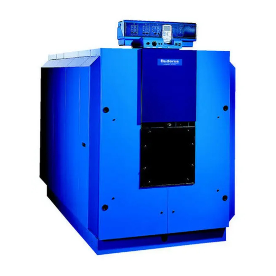
Logano G615
Boilers for oil/gas-fired power burners
WARNING: If installation, adjustment, modification, oper-
ation or maintenance of the heating system is carried out
by an unqualified person, this may result in personal injury
or property damage.
The directions of this installation manual must be followed
precisely.
If support or additional information is required, contact a
qualified service company, service provider or the gas
company.
WARNING:
Observe the safety instructions of this installation manual
before placing the heating appliance in operation.
The operating manual is a component of the technical
documentation and must be handed over to the operator
of the heating system. Explain to the owner or operator
how to use the heating system using the operating
instructions. Make sure that he has been familiarized with
all information required for the operation of the heating
system.
NOTICE: In the Commonwealth of Massachusetts this
boiler must be installed by a licensed plumber or gas fitter.
This manual is available in the English and French lan-
6 720 642 625-00.1O
guage.
Please keep this manual for future reference.
Low-temperature oil/
gas boiler
For contractors
Read carefully prior to
installation and mainte-
nance
Advertisement
Table of Contents

Related Manuals for Buderus Logano G615


Summary of Contents for Buderus Logano G615
- Page 1 This manual is available in the English and French lan- 6 720 642 625-00.1O guage. Please keep this manual for future reference. Logano G615 For contractors Read carefully prior to Boilers for oil/gas-fired power burners installation and mainte-...
-
Page 2: Table Of Contents
Commonwealth of Massachusetts . .10 The oil/gas-fired boiler Logano G615 is available in two variants (disassembled and assembled). Specifications ......11 These installation and service instructions explain the installation and service of both boiler types. - Page 3 Initial burner start-up ....44 11.5 Commissioning log ....45 Logano G615 - Subject to technical modifications...
-
Page 4: Guideline To Symbols And Safety Instructions
B Safeguard sufficient supply of combustion air also for appliances installed at a later date, e.g. kitchen exhaust fans, clothes dryers, and air conditioning units with vent to the outside. Logano G615 - Subject to technical modifications... - Page 5 B If the system overheats or the gas supply does not shut off, do not switch off or disconnect the power supply to the pump. Instead, shut off the gas supply somewhere else separate from the heating system. Logano G615 - Subject to technical modifications...
-
Page 6: Product Description
(hole pattern depends on burner) as accessories from Buderus. The predrilled burner plate is included in the scope of delivery for the Logano G615 with oil or gas-fired fan- assisted burners. During installation and operation of the heating system, observe all national... -
Page 7: Designated Use
Natural Gas (NG) Remark The Logano G615 boiler can be operated with the specified fuels. Select a burner suitable for use with the fuels specified for the Logano G615 boiler. The output figures shown in the Tab. “Technical Data” are nominal power figures. -
Page 8: Operating Conditions
This shunt pump circuit can be controlled either with a Buderus 4000 control or with a third-party This operating condition can be easily achieved by the controller. Failure to ensure that the operating condition is... -
Page 9: Compliance With Standards
Installation Code for Gas Burning Appliances and Equipment, CAN/CSA-B.149 and the applicable local regulations and requirements for the appliance category. The relevant authorities and regulatory bodies must be informed before installation starts. Logano G615 - Subject to technical modifications... -
Page 10: Additional Regulations For Installations In The Commonwealth Of Massachusetts
The sign shall read, in print size no less than appliance or equipment at the completion of the one-half (½) inch in size, “GAS VENT DIRECTLY installation. BELOW. KEEP CLEAR OF ALL OBSTRUCTIONS”. Logano G615 - Subject to technical modifications... -
Page 11: Specifications
2) The filling of the boiler and the system must be undertaken on a separate connector on the return line. 3) The flange corresponds to the order reduced to 212 (DN100), 176 (DN80) or 149 (DN65). Logano G615 - Subject to technical modifications... - Page 12 °F 32.277 32.32 32.359 32.397 32.446 32.495 32.539 32.582 mass flow ( °C) (0.1537) (0.1778) (0.1995) (0.2207) (0.2479) (0.275) (0.2992) (0.3234) rate, oil, partial load 60 % Tab. 4 Technical data and dimensions Logano G615 - Subject to technical modifications...
- Page 13 Example: Safety limit (STB) = 212 °F (100 °C), max. possible supply temperature = 212 – 32 = 180 °F (100 – 18 = 82 °C). 4) Observe all gas regulations and requirements for your country. Logano G615 - Subject to technical modifications...
-
Page 14: Scope Of Delivery
Crate NOTICE: Risk of system damage from impacts. Jacket pack B Crate B The standard delivery of the Logano G615 Thermal insulation Foil pouch oil/gas-fired boiler contains components that are sensitive to shock. Tab. 5 Scope of delivery (block delivery) B During handling protect all electronic and other components against impact. -
Page 15: Positioning The Boiler
121 1/4 9 – 16 (3080) Tab. 7 Boiler assembly tool size 2.3 (complete in the toolbox) For the correct arrangement of the flange when performing the assembly procedure, refer to page 21. Logano G615 - Subject to technical modifications... -
Page 16: Recommended Wall Clearances
The burner door can be hung with the hinges on the right or left. The wall clearance on the hinge side must be at least the burner projection (AB). A distance of AB + 4" (AB + 100 mm) from the wall is recommended. Logano G615 - Subject to technical modifications... -
Page 17: Installing The Boiler On A Boiler Base Or Foundation
3 15/16 × 1 31/32 × 5/16 inches (100 × 50 × 8 mm) or sheet metal with the dimensions 3 15/16 × 13/64 inches (100 × 5 mm). Logano G615 - Subject to technical modifications... -
Page 18: Boiler Block Assembly
The assembly of the boiler block from individual sections is described below. For details on final assembly of the remainder of the boiler, see Chapter 7.3, page 23. Logano G615 - Subject to technical modifications... -
Page 19: Joining The Boiler Block Assembly
The packing grooves must be clean and dry B Evenly coat the hub sealing faces with sealant. for the sealant rope to adhere properly. The next step involves preparing the nipples that will eventually seal the boiler sections. Logano G615 - Subject to technical modifications... - Page 20 Peel the backing 720 42 25-12.1o paper from the sealant rope when inserting Fig. 14 Preparing the center section into the packing groove (do not stretch). Sealing face of the hub Packing springs Logano G615 - Subject to technical modifications...
- Page 21 Use boiler assembly tool 2.3 ( Fig. 4, page 15). B Push pressure flange with clamping nuts onto the tie rods. B Push a tie rod through the top and bottom hubs on the boiler block. Logano G615 - Subject to technical modifications...
- Page 22 20), here too, the flexible sealant rope is interrupted. The boiler section has been equipped with foot wedges for ease of installation. The boiler section foot wedges are also used later for final leveling of the boiler block. Logano G615 - Subject to technical modifications...
-
Page 23: Setting Up The Boiler Block
B Observe all locally applicable occupational health & safety regulations regarding lifting equipment. B Cut the straps. B Remove pallet. 720 42 25-18.1o Fig. 21 Removing the transport safety brace Top hub Bottom hub Transport safety brace Logano G615 - Subject to technical modifications... -
Page 24: Inserting The Supply Pipe (Parts Crate)
Fig. 23 Installing sensor wells Sensor well R ¾ " Sensor well R ½ " 720 42 25-19.1o Fig. 22 Sealing in the supply pipe Flat gasket Flange cover Supply pipe Notch in top boiler hub Logano G615 - Subject to technical modifications... -
Page 25: Inserting The Lower Distribution Tube (Fittings Crate)
B Close off bottom boiler hub with flat gasket and flange Flange cover cover. Lower distribution tube element L The length and number of the lower distribution tube elements depends on the boiler size and can be determined using Table 10 below. Logano G615 - Subject to technical modifications... -
Page 26: Leak Test
Use new nipples and new sealant rope for drain connection. Purge the air from the boiler block via the reassembly. the boiler supply connection with purger. B Pull the boiler back together and repeat the leak test. Logano G615 - Subject to technical modifications... -
Page 27: Boiler Water Connections
B The supply connection flange is required for connecting the supply at a later stage. 720 42 25-24.1o Fig. 27 Fitting a flange Supply connection flange Flat gasket Top boiler hub (return connection) Flat gasket Weld neck flange Logano G615 - Subject to technical modifications... -
Page 28: Installing Draft Diverter, Baffles, And Burner Door
Cleanout cover on the rear section 6 720 6 2 625-25.1o Fig. 28 Positioning the draft diverter Sealant rope joint at the top of the groove Sealant rope Draft diverter Threaded studs Rear section Threaded studs Logano G615 - Subject to technical modifications... -
Page 29: Fitting Burner Door
Hinge lobe (top) 6 720 642 625-28. o Fig. 31 Insert the flue gas baffles (boiler block with 9 sections) Flue gas baffles with sickle profile (sectional baffle) Flue gas baffles with sickle profile (interconnected) Logano G615 - Subject to technical modifications... -
Page 30: Installation Of The Boiler Jacket
B Push thermal insulation under the boiler block. The boiler feet are placed in the cut-outs in the thermal insulation. 6 720 642 625-3 . o Fig. 34 Boiler block with thermal insulation Thermal insulation Logano G615 - Subject to technical modifications... - Page 31 16 17/32" (420) 23 15/64" (590) – 29 59/64" (760) 36 39/64" (930) 45 43/64" (1160) 16 17/32" (420) 23 15/64" (590) 26 49/64" (680) 29 59/64" (760) 36 39/64" (930) Tab. 12 Logano G615 - Subject to technical modifications...
-
Page 32: Fitting The Profile Rails
Fig. 36 Fitting front, rear, and side profile rails Cast lugs Side profile rail Front profile rail (top front) Rear profile rail (top rear) Side profile rail Cast lugs Logano G615 - Subject to technical modifications... - Page 33 There are advantages to routing the burner cable underneath the boiler jacket. To prevent damage to the burner cable while opening the burner door, the burner cable must always be fed down the hinge side. Logano G615 - Subject to technical modifications...
- Page 34 6 720 642 625-39. o Fig. 42 Fitting the remaining side panels Top side profile rail Bottom side profile rail Logano G615 - Subject to technical modifications...
-
Page 35: Fitting Side Panels And Top Covers
26 49/64" (680 mm) 11 boiler sections 30 33/64" (775 mm) 12 boiler sections 33 15/32" (850 mm) 13 boiler sections 20 5/64" (510 mm) 14 boiler sections 15 boiler sections 16 boiler sections Logano G615 - Subject to technical modifications... - Page 36 15 3/4" (400 mm) 12 boiler sections 15 3/4" (400 mm) 13 boiler sections 19 15/16" (485 mm) 14 boiler sections 20 5/64" (510 mm) 15 boiler sections 22 7/16" (570 mm) 16 boiler sections Logano G615 - Subject to technical modifications...
- Page 37 Fig. 48 Fitting the left and right front panels capillary tubes fed to the sensor wells and Burner door panel the sensors placed in the sensor wells (see Chapter 9.1, page 39). Logano G615 - Subject to technical modifications...
-
Page 38: Connecting The Boiler On The Flue Gas Side
Fig. 49 Sealing the vent pipe Vent pipe sealing collar Flue gas temperature sensor Sleeve Vent pipe Hose clamps Draft diverter 2 × Vent pipe diameter, at least 28 22/64 inches (720 mm) Logano G615 - Subject to technical modifications... -
Page 39: Installing The Control Panel
Alignment tabs The flexible hooks must engage with the rectangular Oval holes in the front top boiler cover openings at the rear of the front boiler cover. Cable duct Front top boiler cover Logano G615 - Subject to technical modifications... - Page 40 Take care to ensure proper cable and capillary tube routing. Secure all cables with cable strain reliefs. B Insert cable strain relief with cable inside into the clip frame and secure by closing the lever. Logano G615 - Subject to technical modifications...
-
Page 41: Installing Set Of Temperature Sensors
Logamatic sensor FK or thermostat sensor) are installed in the sensor wells. The manual reset high limit (STB) can be distinguished from the control panel sensor. The sensors must be arranged as follows: Logano G615 - Subject to technical modifications... -
Page 42: Mounting The Burner
Fig. 56, [4]) using the appropriate insulating rings or boiler packing insulation Fig. 56, [3]). B Connect the vent blower connection to the burner to ensure the inspection window remains free of deposits. Logano G615 - Subject to technical modifications... -
Page 43: System Start-Up
11 System start-up You can connect control panel of the 4000 series to the 11.1 Filling the system Logano G615. The commissioning process for the NOTICE: Risk of system damage from different types of control panels is the same. temperature stresses. -
Page 44: Commissioning The System
Fig. 57 Checking that flue gas baffles are seated correctly 11.3 Start up the control panel Please see the accompanying technical documentation for the 4000 series control panel for information about on how to start it up. Logano G615 - Subject to technical modifications... -
Page 45: Commissioning Log
System start-up 11.5 Commissioning log B Sign all start-up work as completed and enter the The Logano G615 can be used with an oil- or gas-fired burner. Fill in the commissioning log for the appropriate relevant date. type of oil or gas burner carefully. -
Page 46: Shutting Down The System
In other dangerous situations, immediately close the main fuel shut-off valve. B Shut off the fuel supply to the burner. Logano G615 - Subject to technical modifications... -
Page 47: System Inspection And Maintenance
B Work on gas components must only be carried out by trained and certified gas The boiler consisting of 16 boiler sections fitters. does not contain any flue gas baffles Chapter 7.9.4, page 29). Logano G615 - Subject to technical modifications... - Page 48 Cleanout cover on the draft diverter B Clean the top and bottom flue gas passages with cleaning brushes #4 and #5 [ Fig. 63]. B Clean the combustion chamber with cleaning brush 8. Logano G615 - Subject to technical modifications...
- Page 49 (60 × 73) Combustion 78 47/64 + 39 3/8 7 7/8 × 3 5/32 chamber 15 -16 A + G + K (2000 + 1000) (200 × 80) Tab. 14 Brush sizes and usage locations Logano G615 - Subject to technical modifications...
-
Page 50: Wet-Cleaning The Boiler
B Heat the boiler water temperature to at least 158 °F (70 °C). B Shut down the boiler. B Allow boiler to cool down, then open burner door. B Brush out the heat exchanger heater. Logano G615 - Subject to technical modifications... -
Page 51: Checking The Operating Pressure
B Ensure that your heating system is bled. B Check the heating system for leaks and the function of the expansion vessel. Logano G615 - Subject to technical modifications... -
Page 52: Inspection And Maintenance Logs
If during inspection work conditions are identified that require additional service and maintenance, perform this work on an as-needed basis. If make-up water is added, the quality of this water must correspond to the specifications in the enclosed operating manual. Logano G615 - Subject to technical modifications... - Page 53 System inspection and maintenance Date:____________ Date:____________ Date:____________ Date:____________ Company stamp/ Company stamp/ Company stamp/ Company stamp/ signature signature signature signature Tab. 16 Continuation Logano G615 - Subject to technical modifications...
- Page 54 Commissioning the heating system Record the final checks of the maintenance work, incl. measurements and test results Check safe and proper operation Confirm professional inspection Company stamp/ Company stamp/ signature signature Tab. 17 Maintenance log book Logano G615 - Subject to technical modifications...
- Page 55 System inspection and maintenance Date:____________ Date:____________ Date:____________ Date:____________ Company stamp/ Company stamp/ Company stamp/ Company stamp/ signature signature signature signature Tab. 18 Continuation Logano G615 - Subject to technical modifications...
-
Page 56: Troubleshooting Burner Faults
If the burner does not restart after three attempts, refer to the technical documentation provided with the burner to find out how to reset it. Logano G615 - Subject to technical modifications... -
Page 57: Spare Parts
B Request spare parts with name and part number using NOTICE: Damage caused by use of spare the spare parts list. parts not supplied by Buderus may not be covered under the manufacturer`s warranty. 6720906688.aa.RS-G615 Fig. 65 Spare part groups Logano G615 Item ( Fig. - Page 58 Spare parts 6720906689.aa.RS-Kesselblock GE615 Fig. 66 Group 1 – boiler block - front Logano G615 Logano G615 - Subject to technical modifications...
- Page 59 Lower distribution tube G615 compl. 2743 long (16 seg.) 67900517 Hinge G615 cpl 70003789 5327460 Hex-head bolt ISO4017 M12x55 8.8 5090262 Washer DIN125-A13-A3K 5883276 Tab. 20 Group 1 – boiler block - front Logano G615 Logano G615 - Subject to technical modifications...
- Page 60 Spare parts View "A" Ansicht "A" View "A" turned 90° Ansicht "A" 90 gedreht M8x12 M10x50 6720906690.aa.RS-Kesselblock GE615 Rückansicht Fig. 67 Group 2 – boiler block - rear Logano G615 Logano G615 - Subject to technical modifications...
- Page 61 Flange RP3/4 Mod11306470, square 130 Exc 5430284 Gasket D94x120x1.5mm (2x) 8 718 572 752 0 Sealing material Silastic 732 90ml tube 5909320 Sealant rope GP10x1070mm long 63020962 Tab. 21 Group 2 – boiler block - rear Logano G615 Logano G615 - Subject to technical modifications...
- Page 62 2x sickle profile 2x sickle profile 1x wave profile 1x wave profile 1x wave profile 1x wave profile 1x wave profile 1x wave profile 6720906691.aa.RS-Kesselblock GE615 Zubehör Fig. 68 Group 3 – boiler block - accessories Logano G615 Logano G615 - Subject to technical modifications...
- Page 63 Thermal insulation vent pipe part 3+4 67902967 Vent pipe seal sleeve set DN360 5354432 Gasket for flue collar DN360 compl. 5354308 Maintenance package G615 verp 63007464 Tab. 22 Group 3 – boiler block - accessories Logano G615 Logano G615 - Subject to technical modifications...
- Page 64 Spare parts M5x16 M12x40 M10x25 St6,3x25 6720906692.aa.RS-Brennertür GE615 Fig. 69 Group 4 – burner door Logano G615 Logano G615 - Subject to technical modifications...
- Page 65 Gasket D13.5x1mm 5752220 Seal ring 13x18x1.5 5883094 Hinge eyelet G615 70003791 5327464 Washer DIN125-A13-A3K 5883276 Sealant rope 18x3800 GP 63020975 Sealing compound brown 63014361 Tab. 23 Group 4 – burner door Logano G615 Logano G615 - Subject to technical modifications...
- Page 66 Spare parts M8x12 M8x12 M8x12 M8x12 M8x12 M8x12 M8x12 M8x12 M8x12 6720906693.aa.RS-Verkleidung GE615 Grundbegestigung Fig. 70 Group 5 – jacket - fastening Logano G615 Logano G615 - Subject to technical modifications...
- Page 67 Top profile rail G615 5932702 Bottom profile rail G615 5932700 Base panel compl. G615 67902663 Flat-head screw ST3.9x9.5 A3T (10x) 7 747 026 999 Tab. 24 Group 5 – jacket - fastening Logano G615 Logano G615 - Subject to technical modifications...
- Page 68 Spare parts M8x12 M8x12 6720906694.aa.RS-Verkleidung GE615 St3,5x22 Fig. 71 Group 6 – sheetmetal parts front/rear Logano G615 Logano G615 - Subject to technical modifications...
- Page 69 Cover clamp strain relief 67903164 Cable clamp 5340450 Flat-head screw ST3.9x9.5 A3T (10x) 7060754 Front cover G615 left cpl 7 747 026 999 Tab. 25 Group 6 – sheetmetal parts front/rear Logano G615 Logano G615 - Subject to technical modifications...
- Page 70 7 12 8 7 10 8 11 10 7 12 11 10 7 7 7 12 10 7 12 7 11 6720906695.aa.RS-Verkleidung GE615 Anordnung Fig. 72 Group 7 – sheet metal parts Logano G615 Logano G615 - Subject to technical modifications...
- Page 71 Top cover cpl 570br G615 (part G) 67902639 Side panel G615 280br left cpl (parts A-l) 67902638 Side panel G615 510br left cpl (part B) 67902634 Tab. 26 Group 7 – sheet metal parts Logano G615 Logano G615 - Subject to technical modifications...
- Page 72 Spare parts St4,8x19 St4,8x19 6720906696.aa.RS-Verkleidung Träger für Regelgerät Fig. 73 Group 8 – sheetmetal parts carriers Logano G615 Logano G615 - Subject to technical modifications...
- Page 73 63045229 Conduit slotted (blue) (1x) 63045226 Top cover for HS 4311/4312 63045225 Burner cable 8M 7079690 Installation material for control panel carrier 63045180 Tab. 27 Group 8 – sheetmetal parts carriers Logano G615 Logano G615 - Subject to technical modifications...
-
Page 74: Index
Fill water.................. 43 Fuels ..................7 Inspection contract .............. 47 Maintenance contract (as-required basis) ...... 47 Make-up water............... 43 Operating pressure, maximum..........8 Safety instructions..............4 Supply temperature..............8 Temperature control............... 8 Transport ................14 Logano G615 - Subject to technical modifications... -
Page 75: Appendix
Manufacturer no. ______________________ Location ______________________ The technical documentation has been handed over to the user. He has been familiarized with the safety instructions, operation and mainte- nance of the system. Date, signature (user) Logano G615 - Subject to technical modifications... - Page 76 United States and Canada Bosch Thermotechnology Corp. 50 Wentworth Avenue Londonderry, NH 03053 Tel. 603-552-1100 Fax 603-584-1681 www.buderus.us U.S.A. Products manufactured by Bosch Thermotechnik GmbH Sophienstrasse 30-32 D-35576 Wetzlar www.buderus.com Bosch Thermotechnology Corp. reserves the right to make changes without notice due to continuing...
Need help?
Do you have a question about the Logano G615 and is the answer not in the manual?
Questions and answers