Table of Contents
Advertisement
Advertisement
Table of Contents

Related Manuals for Trane AquaStream CGWN 205


Summary of Contents for Trane AquaStream CGWN 205
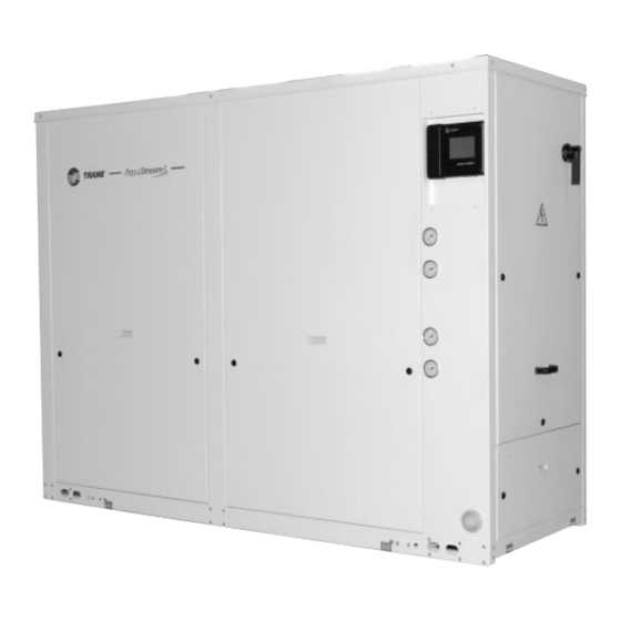
- Page 1 Installation Operation Maintenance Indoor liquid chiller with integrated hydraulic module Water-cooled: CGWN 205 - 206 - 207 - 208 - 209 - 210 - 211 - 212 -213 - 214 - 215 Condenserless: CCUN 205 - 206 - 207 - 208 - 209 - 210 - 211 - 212 - 213 - 214 - 215 CG-SVX06D-E4...
-
Page 2: Trane Air Conditioning And Refrigeration Equipment
[or an ozone depleting substance covered by Montreal Protocol]. The type and quantity of refrigerant per circuit is indicated on the product nameplate Global Warming Potential of the refrigerant implemented in Trane Air Conditioning and Refrigeration Equipment Refrigerant type GWP (1) value... -
Page 3: General Information
7 days of delivery, claiming equipment. The services of a for the described damage. A copy qualified technician should be of this letter must be sent to Trane employed through the medium of a Epinal Operations - Claims team. maintenance contract with a Note: for deliveries in France, even reputable service company. -
Page 4: Table Of Contents
Contents Trane Air Conditioning and Refrigeration equipment Environmental protection - Compliance with F-Gas regulation General information Foreword Warranty Reception About this manual About the unit Refrigerant General data Installation Unit nameplate Installation instructions Handling Minimal installation water content Water treatment... - Page 5 Contents General start-up Preparation Start-up Operation Installation checklist Control and unit operation Weekly start up Weekend shutdown Seasonal shutdown Seasonal start-up Maintenance Maintenance instructions Troubleshooting guide Safety recommendations Maintenance contract Training CG-SVX06D-E4...
-
Page 6: General Data
General Data Table 1 - Water Cooled units: CGWN standard - R410A CGWN CGWN CGWN CGWN CGWN CGWN CGWN Eurovent Performances (1) Net Cooling Capacity (kW) 182.5 217 .0 251.7 283.1 312.1 341.9 373.7 Total Power input in cooling (kW) 42.5 50.2 57 .7... - Page 7 General Data Table 2 - Water Cooled units: CGWN standard - R407C CGWN CGWN CGWN CGWN Eurovent Performances (1) Net Cooling Capacity (kW) 398.6 431.3 466.0 506.4 Total Power input in cooling (kW) 97.0 106.4 117.3 125.5 Evaporator water pressure drop (kPa) Evaporator head pressure available (4) (kPa)
- Page 8 General Data Table 3 - Water Cooled units: CGWN High Efficiency (HE) - R410A CGWN CGWN CGWN 205 HE 206 HE 207 HE Eurovent Performances (1) Net Cooling Capacity (kW) 193.3 227 .4 262.4 Total Power input in cooling (kW) 40.1 47 .9 55.7...
- Page 9 General Data Table 4 - Condenserless units: CCUN standard - R410A CCUN CCUN CCUN CCUN CCUN CCUN CCUN Eurovent Performances (1) Net Cooling Capacity (kW) 166.3 198.1 230.4 257 .7 281.9 311.4 343.8 Total Power input in cooling (kW) 45.6 53.8 62.0 69.8...
- Page 10 General Data Table 5 - Condenserless units: CCUN standard - R407C CCUN CCUN CCUN CCUN Eurovent Performances (1) Net Cooling Capacity (kW) 385.6 417.3 450.4 486.9 Total Power input in cooling (kW) 99.0 108.5 120.5 131.1 Evaporator water pressure drop (kPa) Evaporator head pressure available (4) (kPa)
- Page 11 General Data Table 6 - Condenserless units: CCUN High Efficiency (HE) - R410A CCUN CCUN CCUN 205 HE 206 HE 207 HE Eurovent Performances (1) Net Cooling Capacity (kW) 175.0 206.7 239.1 Total Power input in cooling (kW) 45.6 53.8 62.0 Evaporator water pressure drop (kPa)
- Page 12 General Data Table 7 - Evaporator hydraulic module High head pressure option Nb Pump set Motor (1)(2) (kW) 7 .5 7 .5 11.0 11.0 11.0 11.0 Rated Amps (1)(2) 7 .5 7 .5 11.1 11.1 11.1 14.7 14.7 20.0 20.0 20.0 20.0 Motor RPM...
-
Page 13: Installation
6 pads are supplied as standard with the machine (55x150mm). They should be placed between the supporting floor and the unit to isolate from the ground. Trane does not recommend to install spring isolators. Water drain hole Install a drain hole wide enough to drain away water from the unit in the event of shut-down or repair. -
Page 14: Handling
Installation CAUTION: This unit must be lifted Handling with the outmost care. Avoid shock A specific lifting method is load by lifting slowly and evenly. To recommended as follows: prevent any damage, position the 1. 4 lifting points are built into the lifting bar so that the slings do not unit. - Page 15 Installation Figure 2 - Rigging the unit - CGWN - CCUN (212-215) CG-SVX06D-E4...
- Page 16 Installation Table 9 - Dimensions of recommended slings and swing-bar A (mm) B (mm) C (mm) D (mm) CGWN 205 CGWN 206 CGWN 207 CGWN 208 CGWN 209 CGWN 210 CGWN 211 CGWN 212 CGWN 213 CGWN 214 CGWN 215 CGWN 205 HE CGWN 206 HE CGWN 207 HE...
-
Page 17: Minimal Installation Water Content
Dead band • Water connections: brass • Minimum time between 2 starts Trane will not accept any liability in of a compressor regards of damage due to the use of The following table gives the untreated or improperly treated minimal installation water content... -
Page 18: Water Connections
Installation 2) Condenser side options Water connections • No hydraulic control Before making any connections, • With pump contactors to control a make sure the labeling for entering remote pump (single or dual) and leaving water corresponds to the • With pump integrated hydraulic submittals. - Page 19 Installation Figure 4 - CGWN hydraulic flow chart - without hydraulic module (212-215) Insulated evaporator CW: Chilled water loop Valve for air vent HW: Condensation water loop ¼ SAE Male pressure tab TT: Temperature sensor ¼ SAE Male drain tab Water flow switch Condenser •...
- Page 20 Installation Figure 5 - CCUN hydraulic flow chart - without hydraulic module (205-211) Figure 6 - CCUN hydraulic flow chart - without hydraulic module (212-215) Insulated evaporator CW: Chilled water loop Valve for air vent TT: Temperature sensor ¼ SAE Male pressure tab Water flow switch ¼...
- Page 21 Installation Figure 7 - CGWN hydraulic flow chart - with hydraulic module on both evaporator and condenser sides (205-211) Insulated evaporator CW: Chilled water loop Valve for air vent HW: Condensation water loop ¼ SAE Male pressure tab TT: Temperature sensor ¼...
- Page 22 Installation Figure 8 - CGWN hydraulic flow chart - with hydraulic module on both evaporator and condenser sides (212-215) Insulated evaporator CW: Chilled water loop Valve for air vent HW: Condensation water loop ¼ SAE Male pressure tab TT: Temperature sensor ¼...
- Page 23 Installation Figure 9 - CCUN hydraulic flow chart - with hydraulic module on evaporator side only (205-211) Insulated evaporator CW: Chilled water loop Valve for air vent TT: Temperature sensor ¼ SAE Male pressure tab Pressure gauge ¼ SAE Male drain tab Water flow switch Condenser •...
- Page 24 Installation Figure 10 - CCUN hydraulic flow chart - with hydraulic module on evaporator side only (212-215) Insulated evaporator CW: Chilled water loop Valve for air vent TT: Temperature sensor ¼ SAE Male pressure tab Pressure gauge ¼ SAE Male drain tab Water flow switch Condenser •...
- Page 25 8 = Strainer: avoid to get heat exchangers dirty. All installation must be equipped with efficient strainer in order that only clean water enters into exchanger. If there is no strainer, reserve will be formulated by the Trane technician at the start-up of the unit.
-
Page 26: Refrigerant Line Connections
Installation Refrigerant line connections Piping Maximum distances and refrigerant line diameters between units must be checked according to the configuration and system operating conditions (Chilled water temperature and subcooling). Tables 12-14 provide the maximum acceptable height according to subcooling available and recommended diameters for discharge liquid lines when CCUN condenserless chillers are connected... - Page 27 Installation Figure 14 - Installation configuration - CCUN below remote condenser 1: Discharge line 2: Liquid line Figure 15 - Installation configuration - CCUN above remote condenser 1: Discharge line 2: Liquid line CG-SVX06D-E4...
- Page 28 Installation The minimum required subcooling at the remote condenser level when installed below is defined in the following table. Example : If the remote condenser is 10m below the CCUN and the condensing temperature is 50°C, the refrigerant subcooling leaving the remote condenser shall not be below 4°C.
- Page 29 Installation Table 12 - Recommended discharge line diameters for horizontal risers (Circuit 1) Required discharge pipe diameter - Circuit 1 Unit size CCUN 7/8" 1"1/8 1"3/8 CCUN 7/8" 1"1/8 1"3/8 CCUN 7/8" 1"1/8 1"3/8 CCUN 1"1/8 1"3/8 1"5/8 CCUN 1"1/8 1"3/8 1"5/8 CCUN...
- Page 30 Installation Table 14 - Recommended liquid line diameters for vertical or horizontal risers (Circuit 1) Required liquid line pipe diameter - Circuit 1 Unit size CCUN 5/8" 7/8" 1"1/8 CCUN 5/8" 7/8" 1"1/8 CCUN 5/8" 7/8" 1"1/8 CCUN 7/8" 1"1/8 1"3/8 CCUN 7/8"...
- Page 31 These operations have to be performed by a specialist. The results have to be written on a start up record by the Trane engineer or the client's specialist who has performed this start up. The quantity of refrigerant and oil added are at the client's charges.
- Page 32 Installation High pressure Pressure relief valve - CCUN The remote condenser must have a Above the maximum system service pressure equal to or higher refrigerant charge, it is than the high service pressure (44.5 recommended to install a pressure bar for CCUN 205-211 and 29.5 bar relief valve.
-
Page 33: Winter Freeze Protection
Installation Winter freeze protection CAUTION: - There is a risk of freeze-up of the During negative ambient air evaporator circuit due to internal temperature chilled water piping refrigerant migration if the must be fully insulated. Ensure that condenser circuit is maintained at a all safeties are taken to prevent frost low temperature (below 0°C) for a damage during negative ambient air... -
Page 34: Electrical Connections
Installation Electrical connections CAUTION: 1. Cabling must comply with local CAUTION: standards. The type and location 1. The greatest care should be taken of fuses must also comply with when cutting through passages standards. As a safety measure, and installing electric wiring. fuses should be visibly installed, Under no circumstances should close to the unit. - Page 35 Installation Figure 21 - CGWN and CCUN main power supply connection (1) (212-215) 1 = Power cable inlet 2 = Disconnect switch (1) shown here : CGWN. Components in same location on CCUN. CG-SVX06D-E4...
- Page 36 Installation When ordered, the outdoor air The sensing bulb is extended, on the sensor electronics is factory-mounted sensor side, outside the unit. These and wired. It is located inside the wires can be spliced with two control panel. The IPC bus is factory- 0.75mm.
- Page 37 Installation Make sure phase order is correct. Should the compressor be noisy, reverse Note 2 phases. Figure 24 - Outdoor ambient air sensor connection CG-SVX06D-E4...
- Page 38 Installation directly to the terminal block for the Interconnection optional fan relay cards. between CCUN and CAUTION: Remote Condenser Power supply to the outdoor fan The CCUN has the capability to relays shall not be provided from the control the fan staging of the remote CCUN unless special care to the condenser if the option is taken.
- Page 39 Installation Check also compressor suction Operating range superheat for being close to 5 or 6°C CAUTION: Maximum operating time for low chilled leaving water for low condensing water outlet is temperature to minimize compressor 1 minute. The compressor shall discharge temperature. For very high become noisy.
- Page 40 The installer terminals to ground complies with must check all the following points standards and regulations in force before calling in the Trane Servicing • Check that unit voltage and frequency supplied match rated Department to put the equipment...
- Page 41 OFF time for a split unit (CCUN • Put the plexiglass supplied by with remote condenser). See the Trane in front of the power "Compressor oil level at oil terminal equalization line for correct level. • Ensure all water and refrigerant •...
- Page 42 General Start-up Electrical power wiring: Operating parameters statement • Check all the electrical terminals • Switch on main power supply are tight switch • Set-up compressors overload • Start the water pump(s) and check relays there is no cavitation • Set-up fan-motors overload relays •...
- Page 43 • Phase imbalance should not be unit available pressure. It must be greater than 2%. in accordance with Trane order • The voltage supplied to motors write-up. should be within 5% of the rated voltage on the compressor •...
- Page 44 General Start-up Figure 30 - Standard and High Efficiency units evaporator pressure drop EWFR : Evaporator Waterflow Rate EWPD : Evaporator Water Pressure Drop Figure 31 - Standard units condenser pressure drop CWFR : Condenser Waterflow Rate CWPD : Condenser Water Pressure Drop CG-SVX06D-E4...
- Page 45 General Start-up Figure 32 - Evaporator available pressure - Standard and High Efficiency units - Low head pressure - Single pump EWFR : Evaporator Waterflow Rate EWPD : Evaporator Water Pressure Drop Figure 33 - Evaporator available pressure - Standard and High Efficiency units - Low head pressure - Dual pump EWFR : Evaporator Waterflow Rate EWPD : Evaporator Water Pressure Drop...
- Page 46 General Start-up Figure 34 - Evaporator available pressure - Standard and High Efficiency units - High head pressure - Single pump EWFR : Evaporator Waterflow Rate EWPD : Evaporator Water Pressure Drop Figure 35 - Evaporator available pressure - Standard and High Efficiency units - High head pressure - Dual pump EWFR : Evaporator Waterflow Rate EWPD : Evaporator Water Pressure Drop...
- Page 47 General Start-up Figure 36 - Condenser available pressure - Standard and High Efficiency units - Low head pressure CWFR : Condenser Waterflow Rate CWPD : Condenser Water Pressure Drop Note: Pumps remain the same when variable speed drive option is selected. Figure 37 - Condenser available pressure - Standard and High Efficiency units - High head pressure CWFR : Condenser Waterflow Rate...
- Page 48 General Start-up Figure 38 - Condenser available pressure - Standard units - Variable speed pump (212-215) CWFR (l/s) CWFR : Condenser Waterflow Rate CWPD : Condenser Water Pressure Drop CG-SVX06D-E4...
- Page 49 General Start-up When ethylene glycol is added in the chilled water circuit the following adjustment factors have to be taken in account. Figure 39 - Ethylene Glycol recommended concentration LWT (°C) LWT: Lowest water temperature CG-SVX06D-E4...
- Page 50 General Start-up Figure 40 - Propylene Glycol recommended concentration LWT (°C) LWT: Lowest water temperature CG-SVX06D-E4...
- Page 51 General Start-up Table 20 - Correction factors to apply when glycol is used in water loops Glycol Concentration % Performance Evaporator Condenser Fluid Type Evaporator Condenser F-CC F-PI F-FLEVP F-PDEVP F-FLCDS F-PDCDS Water only 1.00 1.00 1.00 1.00 1.00 1.00 0.99 1.00 1.02...
- Page 52 [kW] (found in the General data of fluid: please contact your local section) Trane sales representative. A relief 2. Power Input with glycol [kW] = F- valve is located at pump suction PI x Power Input water [kW]...
-
Page 53: Installation Checklist
Check that electrical connections are in accordance with information on manufacturer's identification plate Check direction of rotation using phasemeter Comments ………………………………………………………………………………………………………………………………………………… ………………………………………………………………………………………………………………………………………………… ………………………………………………………………………………………………………………………………………………… ………………………………………………………………………………………………………………………………………………… ………………………………………………………………………………………………………………………………………………… Signature:…………………………………………………………………….Name:…………………………………...………………… Order N°: …………………………………………………………………………………………………………………………………… Work site: …………………………………………………………………………………………………………………………………… Please return to your local Trane Service Office CG-SVX06D-E4... -
Page 54: Control And Unit Operation
Trane does not recommend draining described in the CGWN-CCUN the unit, due to the fact that it User Manual (See "Clock" menu) increases tube corrosion. -
Page 55: Seasonal Start-Up
Operation Seasonal start-up • Check water flows and interlocks. • Check Ethylene glycol concentration in the chilled water circuit if glycol presence is required • Check operational set points and performance • Calibrate controls • Check operation of all safety devices •... -
Page 56: Maintenance Instructions
Maintenance Maintenance Instructions Inspection visit after the first 500 hours of operation from unit The following maintenance start up instructions are part of maintenance • Carry out oil analysis operations required for this • Carry out leak test equipment. A qualified technician is •... - Page 57 Calibrate controls and pressure Any use of oils not meeting transducer specifications recommended by • Check operation of all safety Trane is the responsibility of the user devices only, who thereby is liable to • Inspect contacts and tighten warranty loss.
-
Page 58: Troubleshooting Guide
Check thermal insulation and air-tightness of areas requiring air-conditioning. E) Loss of oil in compressor Oil level too low in indicator. Not enough oil. Contact Trane office before to order oil Gradual fall in oil level. Filter drier clogged. Replace filter drier. Suction line too cold. - Page 59 Maintenance F) Compressor noisy Compressor knocks. Components broken in compressor. Change compressor. a) Check superheat setting and fixing of expansion valve a) Uneven liquid flow. Suction duct abnormally cold. bulb. b) Expansion valve locked in open position. b) Repair or replace. G) Insufficient cooling capacity Thermostatic expansion valve "whistles".
-
Page 60: Safety Recommendations
Maintenance Safety recommendations Training To avoid accidents and damage, the The equipment described in this following recommendations should manual is the result of many years of be observed during maintenance and research and continuous service visits: development. To assist you in obtaining the best use of it and 1. - Page 61 Notes CG-SVX06D-E4...
- Page 62 Notes CG-SVX06D-E4...
- Page 63 Notes CG-SVX06D-E4...
- Page 64 Supersedes CG-SVX06C-E4_0908 Trane has a policy of continuous product and product data improvement and reserves the right to change design and specifications without notice. Only qualified technicians should perform the installation and servicing of equipment referred to in this publication.
Need help?
Do you have a question about the AquaStream CGWN 205 and is the answer not in the manual?
Questions and answers