Advertisement
Table of Contents
- 1 Table of Contents
- 2 General Information
- 3 Safety Precautions
- 4 Nomenclature
- 5 Dimensions
- 6 Performance Data
- 7 Unit Installation
- 8 Electrical Installation
- 9 Wiring Diagram
- 10 Pre-Start-Up
- 11 Unit Operation
- 12 Module Control System
- 13 Building Control System
- 14 Troubleshooting
- 15 Maintenance
- Download this manual
Installation, Operation and
Maintenance
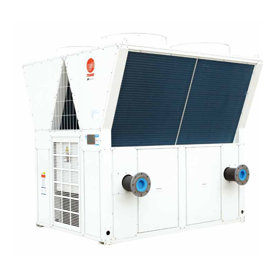
Modular Air-Cooled Chiller (Heat Pump) Unit
CXAJ/CGAJ
Only qualified personnel may install and maintain the unit. The installation, start-up and maintenance of heating,
ventilating and air-conditioning unit will be hazardous, and the operator shall have specific knowledge and training.
Improper installation, adjustment or change of the unit by an unqualified person will result in death or serious injury.
When operating the unit, pay attention to all precautions in the documents and the tags and labels attached to the
unit.
Jan. 2016
Safety Warning
690134220001
PKGP-SVX06A-EN
Advertisement
Table of Contents


Need help?
Do you have a question about the CXAJ series and is the answer not in the manual?
Questions and answers