Table of Contents

Related Manuals for Trane CGWH 115


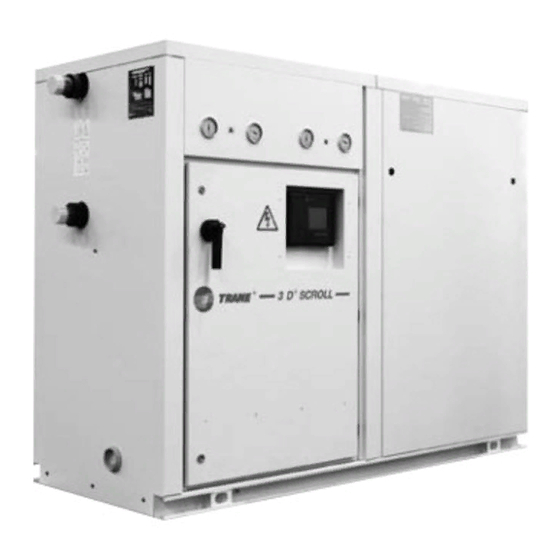
Summary of Contents for Trane CGWH 115
- Page 1 Installation Operation Maintenance CGWH Packaged Water-cooled liquid chiller CCUH Condenserless liquid chiller Sizes 115 - 120 - 125 - 225 - 230 - 235 - 240 - 250 To be used with the user guide of CH530 scroll chiller controls CGWH-SVX01D-E4...
-
Page 2: General Information
Trane observed during maintenance and CGWH/CCUH chillers. They do not service visits: contain full service procedures 1. - Page 3 2 inspections, does not conform to the rules of this including leak detection, per year manual, it may entail cancellation in the EU. Contact your local Trane of warranty and liabilities by the Service team. manufacturer. (1) GWP = global warming potential...
-
Page 4: Table Of Contents
Contents General Information Installation Unit nameplate Installation instructions Handling Minimum water volume Refrigerant lines CCUH Refrigerant line connections - CCUH and remote condenser Winter freeze protection Water treatment Compressor sequencing Interconnection between CCUH and remote condenser Electrical connections General data General start-up Preparation Start-up... -
Page 5: Installation
The unit power rating is shown, and obstruction. Submittals are available power supplies should not deviate by on request from your local Trane more than 5 % from the rated power. Sales Office. Compressor motor amperage is shown in box I.MAX. -
Page 6: Minimum Water Volume
Trane technician at the start-up of the 4. Stop valves: isolate chillers and water unit. The strainer used must be able circuiting pump during maintenance to stop all particles with a diameter operations. -
Page 7: Refrigerant Lines Ccuh
Installation Refrigerant lines CCUH Insulation of refrigerant lines The minimum volume can be determined by using the following Insulate refrigerant lines from Calculating and fixing the capacity formula : Volume = Cooling capacity building itself to avoid transmission of refrigerant lines is necessary x Time x highest capacity step (%) / to building structure of vibrations to assure the oil return to the... -
Page 8: Refrigerant Line Connections - Ccuh And Remote Condenser
Installation Refrigerant line connections - Figure 3 - Installation configuration - CCUH and remote condenser at the same level CCUH + remote condenser Piping Maximum distances and refrigerant line diameters between units must be checked according to the configuration and system operating conditions (Chilled water temperature and subcooling). - Page 9 Installation The minimum required subcooling For refrigerant piping longer than necessary. It has to be located on the at the remote condenser level when 50 m (distance of the condensing suction side. installed below is defined in the unit to the evaporator), a pressure following table.
-
Page 10: Winter Freeze Protection
Installation Winter freeze protection CAUTION: There is a risk of freezeup of the evaporator During negative ambient air circuit due to internal refrigerant temperature chilled water piping migration if the condenser circuit must be fully insulated. Ensure that is maintained at a low temperature all safeties are taken to prevent frost (below 0°C) for a long period during damage during negative ambient air... -
Page 11: Water Treatment
Installation Water treatment Trane will not accept any ability in regards of damage due to the use Untreated or insufficiently treated of untreated or improperly treated water, if used in this unit, may water or from the use of saline or cause scale, slime or algae to brackish water. -
Page 12: Interconnection Between Ccuh And Remote Condenser
Trane provides a single power supply which includes the transformer. Warranty reserves will be formulated if a transformer, not supplied by Trane, is installed inside the electric panel CGWH-SVX01D-E4... - Page 13 Installation Table 11 - Control output relays (CCUH) Fan 1 Fan 2 Fan 3 Fan 4 Fan 5 Fan 6 Output relay Quantity of fans Low Speed High Speed Single speed Fan option 3&4 Two fan speed first fan 3&4 Single speed only fans Two fan speed first fan Single speed only fans...
-
Page 14: General Data
General data Table 14 - R407C Refrigerant CGWH CGWH CGWH CGWH CGWH CGWH CGWH CGWH Eurovent Performances (1) Gross cooling capacity CGWH (1) 51.8 64.9 92.1 104.5 117.4 129.7 157.1 Gross power input CGWH (1) 13.8 17.6 21.3 24.3 27.9 31.3 41.9 Gross EER CGWH (1) - Page 15 General data Table 15 - R407C Refrigerant CCUH CCUH CCUH CCUH CCUH CCUH CCUH CCUH Eurovent Performances (1) Gross cooling capacity CCUH (2) (kW) 51.3 64.3 77.3 103.2 115.4 128.4 154.7 Gross power input CCUH (2) (kW) 14.2 17.9 21.7 28.8 32.6 35.9...
-
Page 16: General Start-Up
(See • Put the plexiglass supplied by components they drive submittals) Trane in front of the power • Water flow control checking: • Chilled water circuit ready terminal. decrease the water flow and to operate, filled with water, •... - Page 17 • chilled water pressure drops • Check all the pressostats, through evaporator. It must be • Check and set-up the CH530 in accordance with Trane order control module write-up, • Test and start-up without the • superheat: difference between electrical power.
- Page 18 It must 14. The refrigerant complement be sent as soon as possible to be in accordance with Trane will be charged according to the the nearest Trane office. order write-up. diameter and the length of the •...
- Page 19 7.93 3.63 4.55 5.43 6.09 6.53 7.43 7.43 8.95 Table 18 - Condenser pressure drop (CGWH) Water flow - l/s CGWH 115 CGWH 120 CGWH 125 CGWH 225 CGWH 230 CGWH 235 CGWH 240 CGWH 250 1.34 1.68 2.01 2.17 2.33...
- Page 20 [kW]) x 0.239 x (1 / of fluid: please contact your local glycol [Litres/sec] = F-FLEVP x Delta T Condenser [°C]) Trane sales representative. Cooling capacity with glycol [kW] x 0.239 x (1 / Delta T Evaporator [°C]) CGWH-SVX01D-E4...
-
Page 21: Operation
Operation Control System • Check operation of machines/ compare conditions of operation The control is through the CH530 against original commissioning control module. data. • Stop the unit with the CH530 by Unit operations pushing «Stop». • Check the chilled water pump(s) •... -
Page 22: Maintenance
Trane is the responsibility of the and costly breakdown. Keep • Check operation of machines/ user only, who thereby is liable service records up to date, showing compare conditions of operation to warranty loss. -
Page 23: Installation Checklist
Check available cooling charge (50% of rated installation load) o Check with other trades handling installation works Comments: ..........................................................................................................................................................Signature: ..................Name................... Order N°: ....................................Work site: ....................................Please return to your local Trane Service Office CGWH-SVX01D-E4... - Page 24 Check available cooling charge (50% of rated installation load) q Check with other trades handling installation works Comments: ..........................................................................................................................................................Signature: ..................Name................Order N°: ....................................Work site: ....................................Please return to your local Trane Service Office CGWH-SVX01D-E4...
-
Page 25: Troubleshooting Guide
Troubleshooting guide These are simple diagnostic hints. If there is a breakdown, the Trane Service office should be contacted for confirmation and assistance. Problems symptoms Problem cause Action recommended A) The compressor does not start up Compressor terminals are live but motor does Motor burned out. - Page 26 E) Loss of oil in compressor Oil level too low in indicator. Not enough oil. Contact Trane Office before to order oil Gradual fall in oil level. Filter drier clogged. Replace filter drier. Suction line too cold.
- Page 27 Problems symptoms Problem cause Action recommended I) Suction pressure too high Compressor operates continuously. a) Expansion valve too far open. Check system. Suction duct abnormally cold. b) Expansion valve locked in open position. a) Check for superheat and check that Refrigerant flows back to compressor.
- Page 28 Trane optimizes the performance of homes and buildings around the world. A business of Ingersoll Rand, the leader in creating and sustaining safe, comfortable and energy efficient environments, Trane offers a broad portfolio of advanced controls and HVAC systems, comprehensive building services, and parts.For more information, visit www.Trane.com.
Need help?
Do you have a question about the CGWH 115 and is the answer not in the manual?
Questions and answers