
Related Manuals for AIRLESSCO EZ Rent 570


Summary of Contents for AIRLESSCO EZ Rent 570
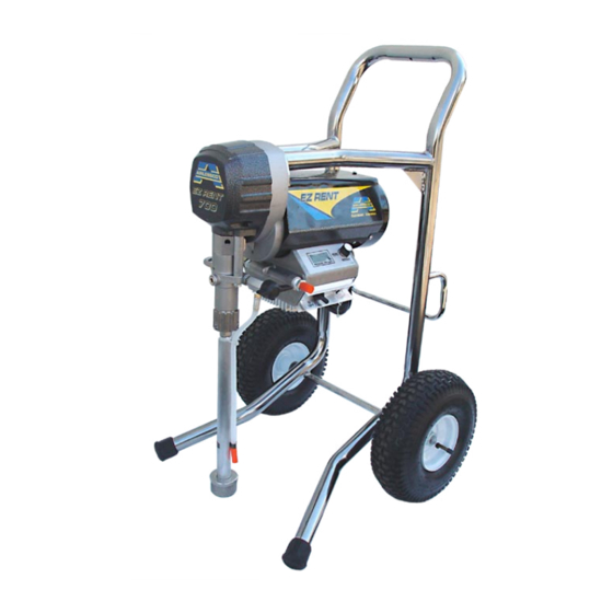
- Page 1 ® IRLESS AINT PRAYER ERVICE PERATION ANUAL AIRLESSCO EZ Rent 570 &700 001-794 Sept 08...
-
Page 2: Table Of Contents
26. Pressure Control Box ..........25 Pressure Control Box ............25 27. LCD................26 Replacement of Electrical Components ......26 Troubleshooting- Machine Does Not Start ...... 27 EZ Series Quick Reference Guide ........28 Notes ................29 Airlessco Accessories ............. 30... -
Page 3: Introduction
NOTE - Identifies essential procedures or extra information. All Service Procedures to be performed by an Authorized Airlessco Service Center ONLY. NO MODIFICATIONS or alterations of any AIRLESSCO Equipment or part is allowed. -
Page 4: Warnings
WARNINGS NOTE TO PHYSICIAN: Injection in the skin is a traumatic MEDICAL ALERT - Airless Spray Wounds injury. It is important to treat the injury surgically as soon as If any fluid appears to penetrate your skin, get EMERGENCY possible. DO NOT DELAY treatment to research toxicity. Tox- MEDICAL CARE AT ONCE. - Page 5 WARNINGS - CONTINUED HOSES GROUNDING Tighten all fluid connections securely before each use. High Ground the sprayer and other components in the system pressure fluid can dislodge a loose coupling or allow high to reduce the risk of static sparking, fire or explosion which pressure spray to be emitted from the coupling and result in can result in serious bodily injury and property damage.
- Page 6 WARNINGS - CONTINUED AVOID COMPONENT RUPTURE PREVENT STATIC SPARKED FIRE/ EXPLOSIONS This sprayer operates at 3000 psi (205 bar). ALWAYS be ALWAYS be sure all equipment and objects being sprayed sure that all components and accessories have a maximum are properly grounded. working pressure of at least 3000 psi to avoid rupture ALWAYS ground sprayer, paint bucket and object being which can result in serious bodily injury including injection...
-
Page 7: Flushing
FLUSHING 1. NEW SPRAYER 5. STORAGE Your unit was factory tested in an oil solution which was left Oil-base paint: Flush with mineral spirits. in the pump. Before using oil-base paint, flush with mineral spirits only. Water-base paint: Flush with water, then mineral spirits and Before using water-base paint flush with mineral spirits, leave the pump, hose and gun filled with mineral spirits. -
Page 8: Setting Up
Fill the Packing Nut/Wet Cup with 5 drops of 5. FLUSH THE SPRAYER Airlessco Throat Seal Follow “Flushing Procedure” on page 5 of this manual. Oil (TSO). 1. LEARN THE FUNCTIONS OF THE (Prime/PR Valve) Used to relieve pressure CONTROLS. -
Page 9: Starting Up
WARNING 4. ADJUSTING THE PRESSURE Be sure to relieve pressure in the pump after filling with Airlessco Pump Conditioner. a. Turn the Pressure Control Knob Clockwise to increase pressure and counterclockwise to decrease pressure. b. Always use the lowest pressure necessary to completely AVOIDING TIP CLOGS atomize the material. -
Page 10: Pressure Relief Procedure
Airlessco Service Center. DAILY MAINTENANCE 1. Keep the displacement pump packing nut/wet cup lubricated with Airlessco TSO (Throat Seal Oil) at all times. The TSO helps protect the rod and the packings. 2. Inspect the packing nut daily. Your pump has a patented Triple Life Packing System. Packing life will be extended a minimum of three times if the following "Packing Adjustment"... -
Page 11: Airless Spray Gun Operation
SPRAY FIG. 7 Attach spray gun to airless unit and tighten fittings securely. Set the gun safety latch. (Also may be called gun safety lock, or trigger lock) * The gun safety latch should always be set when the gun is not being triggered. -
Page 12: Airless Spray Gun
AIRLESS SPRAY GUN FIG. 11 PARTS LIST FIGURE 11 Item No. Part No. Description 120-530* Gun Seat Assembly 120-535* Gasket-Seat 120-520* Needle Assembly 120-529 Gun Seat Adapter 120-562 Trigger Guard 120-539 Pivot Trigger Pin 120-509 Gun Head 120-540 Actuator Pin (2) 120-536 Gun Plate 120-038*... -
Page 13: Airless Spray Gun Troubleshooting
AIRLESS SPRAY GUN TROUBLESHOOTING DEFECTS CAUSE CORRECTION Coarse spray Low pressure Increase the pressure Excessive fogging High pressure Reduce the pressure to satisfactory pattern distrabution (overspray) Material too thin Use less thinner Patten too wide Spray angle too large Use smaller spray angle tip Pattern too narrow Spray angle too small Use larger spray angle tip (if coverage is OK, try tip in same... -
Page 14: Tip Selection Guide
TIP SELECTION GUIDE Spray tip selection is based on paint viscosity, paint type, & be sprayed through the tip. Do not use a tip larger than job needs. For light viscosities (thin paints), use a smaller maximum pump flow rate or capacity the sprayer can tip;... -
Page 15: Electric Motor Maintenance
ELECTRIC MOTOR MAINTENANCE 1. LUBRICATION - This motor is supplied with pre- TO CHANGE THE BRUSHES: lubricated ball bearings, lubricated for the life of the 1. Unplug the machine. bearing. 2. Remove the cover over the motor (if applicable.) 2. MOTOR BRUSHES - need periodic inspection and 3. -
Page 16: Field Troubleshooting
FIELD TROUBLESHOOTING PROBLEM CAUSE SOLUTION Unit doesn’t prime Airleak due to: •Loose suction nut • tighten suction nut • Worn o-rings • replace o-ring (106-018) on suction seat & o-ring (106-017) below suction seat • Hole in suction hose • replace suction hose Stuck or fouled balls •... -
Page 17: Servicing The Fluid Pump
7. Tighten packing nut clockwise until resistance is felt against the Belleville Springs, go 3/4 of a turn more. Put five drops of Airlessco Throat Seal Oil in the packing nut. 8. Run the machine at full pressure for several minutes. -
Page 18: Servicing The Outlet Valve
Before reinstalling the outlet seat support, apply two drops of Loctite No. 242 (blue) on the threads & torque to 20 ft-lbs. NOTE: Airlessco LP pump tool kit 188-197 is required for this task. Kit includes: Tightening Bar (189-211), Packing Removal Tool (331-465), Piston Holder (331- 195), 3/8”... -
Page 19: Packing Replacement Procedures
PACKING REPLACEMENT PROCEDURES 13. Take the packing holder & replace the white O-ring & DISASSEMBLY OF THE FLUID PUMP the black O-ring with new ones from the packing kit. REFER TO FIGURE 17 & 18 14. Slide the packing holder over the top of the upper 1. -
Page 20: V-Packings
PACKING REPLACEMENT PROCEDURES FIG. 18 PARTS LIST FIGURE 17 & 18 PARTS LIST FIGURE 17 & 18 CONT. Item No. Part No. Description Item No. Part No. Description 331-014 Male Gland 331-708 Piston 331-016 Packing Polyethylene 331-018 Spacer 331-308 Female Adaptor 331-025 Belleville Springs 331-011... -
Page 21: Gear And Pump Assembly
GEAR AND PUMP ASSEMBLY FIG 19 WARNING DO NOT OPERATE WITHOUT COVER GUARD IN PLACE PARTS LIST FIGURE 19 Item No. Part No. Description 100-381 Bolt (2) 100-380 Shoulder Bolt (2) 331-088 Retaining Ring 331-490 Motor .60HP 331-491 Motor .90HP 331-117 Sleeve 119-028... -
Page 22: Lo-Boy Models
LO-BOY MODELS FIG. 21 1, 2, 3 PARTS LIST FIGURE 21 PARTS LIST FIGURE 21 CONT Item No. Part No. Description Item No. Part No. Description 331-785 305-039 Spacer (2) 331-786 Fan Cover 331-337 Rubber Edge (2) 117-090 Fan Cover Screws (3) 117-044 Knob 117-129... -
Page 23: Hi-Boy Models
HI-BOY MODELS FIG. 22 PARTS LIST FIGURE 22 PARTS LIST FIGURE 22 CONT Item No. Part No. Description Item No. Part No. Description 331-795 Motor Cover 143-029 Collar (2) 331-788 Bolt (.9HP) 113-019 10” Wheel (2) 331-337 Rubber Edge 113-030 Spacer (2) 117-044 Knob... -
Page 24: Suction Assemblies
SUCTION ASSEMBLIES LO-BOY AND CARRY CHASSIS (331-238) HI-BOY CHASSIS (331-284) FIG. 23 FIG. 24 PARTS LIST FIGURE 23 PARTS LIST FIGURE 24 Item No. Part No. Description Item No. Part No. Description 331-290 Suction Hose Assy 331-090R Fitting 331-217 Inlet Strainer 331-034 Suction Nut 331-035... -
Page 25: Pressure Control Assembly Calibration
PRESSURE CONTOL ASSY CALIBRATION NOTE: ANYTIME A SENSOR OR PRESSURE CONTROL ASSEMBLY (BOARD) OR BOTH ARE REPLACED, THE FOLLOWING CALIBRATIONS MUST BE PERFORMED. NOTE: PRESSURE CONTROL ASSEMBLIES (BOARDS) ARE NOW BEING EQUIPPED WITH A GREEN GROUNDING WIRE ATTACHED. CONTECT THE GROUNDING WIRE TO TERMINAL BOX USING THE SAME SCREW THAT HOLDS THE GROUNDING WIRE FROM THE POWER CORD. -
Page 26: Electrical System
ELECTRICAL SYSTEM - EZ SERIES FIG. 25 BLACK GREEN & A2 A1 INHIBIT SWITCH S1 S2 LCD ZERO PRESSURE LCD SET ON-SL PHASE LIMIT P-ZR SENSOR DISPLAY ZERO POWER YELLOW LIGHT LIGHT PARTS LIST FIGURE 25 Item No. Part No. Description 331-168 Electrical Cord 110V... -
Page 27: Pressure Control Box
EZ SERIES PRESSURE CONTROL BOX (331-324) FIG. 26 2, 3, 4 7, 8 PARTS LIST FIGURE 26 PARTS LIST FIGURE 26 CONT Item No. Part No. Description Item No. Part No. Description 101-482 Control Label (PSI/BAR) 120-021 301-002 100-029 Plated Plug 115-068 O-Ring 331-161... -
Page 28: Replacement Of Electrical Components
REPLACEMENT OF ELECTRICAL COMPONENTS WARNING: ALWAYS UNPLUG THE ELECTRICAL CORD BEFORE SERVICING MACHINE! NOTE: ANYTIME THE PRESSURE CONTROL ASSEMBLY, SENSOR, OR BOTH ARE REPLACED, PERFORM THE CALIBRATIONS. PRESSURE CONTROL ASSEMBLY LIQUID CRYSTAL DISPLAY (LCD) (ELECTRICAL CONTROL BOARD) 1. Lower pressure control assembly as described above. 2. -
Page 29: Troubleshooting- Machine Does Not Start
If the motor is still hot to the touch, allow it to cool and then retest. If the motor is cool and there is not continuity on the red leads, contact Airlessco Technical Support to repair/replace the thermal coupler. Continuity shows that the motor's thermal coupler has not tripped. Proceed to step six. -
Page 30: Ez Series Quick Reference Guide
Note: Turn unit ON. Turn pressure control 2B. Lock gun trigger safety lock knob to low pressure. (Airlessco gun shown) 2A. Lift suction tube and return tube out of Note: Plug into 3 pronged grounded electri- paint and hold over paint bucket. Any cal outlet. -
Page 31: Notes
NOTES... -
Page 32: Airlessco Accessories
Gun Nut “G” Thread 7/8-14 032-011 100-010 1/4" Hose Connector 100-009 3/8" Hose Connector "F to G" Gun adapter to attach Graco tips to Airlessco guns. ® For a complete listing of all available accessories see 032-012 the Airlessco Accessories Catalog, Part # 001-357.
Need help?
Do you have a question about the EZ Rent 570 and is the answer not in the manual?
Questions and answers