
Related Manuals for Lite-Puter CX-5


Summary of Contents for Lite-Puter CX-5
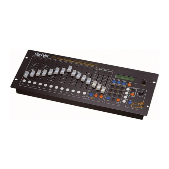
- Page 1 ISO 9001 CERTIFIED CX-5 DMX Intelligent Lighting Controller ¡i User Manual¡j Lite-Puter Enterprise Co., Ltd. Website: http://www.liteputer.com.tw E-mail: litecom@ms2.hinet.net...
-
Page 2: Table Of Contents
ISO 9001 CERTIFIED Index: Chapter 1. The main function of CX-5 1-1 The features of CX-5................... 3 1-2 Power ....................... 4 1-3 Signal input/output ..................4 1-4 Introduction of the functions ................. 5 Chapter 2. How to select different scanners 2-1 How to set different scanners............... - Page 3 ..........................30 Chapter 9. MIDI 9-1 Introduction of MIDI................. 31 9-2 Set up MIDI channel of CX-5 ..............32 9-3 How to store 24 different "SCENE" in MIDI memory........ 33 Chapter 10. How to call out pattern built in the program 10-1 Explanation of the pattern built in the program..........
-
Page 4: Chapter 1. The Main Function Of
There is a “LED” indicator beside every function key for reminding users to know to current condition and for following operation. Compatibility: CX-5 can control any kind of lighting fixtures and has a data bank of more than 100 famous fixtures inside. NOTE: Please make sure the protocol of your scanner is DMX signal, 8 bit and not over 14 channel first. -
Page 5: Power
MIDI : MIDI IN / MIDI OUT l DMX output¡G Standard DMX-512 output, control channel 1 to channel 168. LAMP NO. USE CH. 1-14 15-28 29-42 43-56 57-70 71-84 LAMP NO. USE CH. 85-98 99-112 113-126 127-140 141-154 155-168 CX-5 [EUM-B]... -
Page 6: Introduction Of The Functions
It means “EDIT MODE” when the LED is dark. (P1..P12 is the on / off switch of the lighting fixtures.) “P1 … P12” (HOT KEY) : IMPORTANT ! (1) In “EDIT MODE” , “P1… P12” means the “ON” or “OFF” switch of LAMP1… 12 (2) In “RUN MODE” , “P1… P12” means: CX-5 [EUM-B]... - Page 7 (A preset of manufacturer: P1= MACRO 1… P12= MACRO 12) <d>. at LEARN function: “P1… P12” can load any set of data from LEARN 1… 50 (A preset of manufacturer: P1 = LEARN 1 ... P12 = LEARN 12) CX-5 [EUM-B]...
-
Page 8: Chapter 2. How To Select Different Scanners
1¡G LITE PUTER Press ‘ ‘ o r ‘ ‘ key STEP-3 ¡G Use ” -“ or “ + ” to find your scanner and press ”ENTER” LITE PUTER SCAN Press ‘ ‘ o r ‘ ‘ key CX-5 [EUM-B]... -
Page 9: How To Define The Format Of Lighting Fixtures By User
STEP-4 : Press “ENTER” to confirm. USER DEFINE LAMP TILT =CHANNEL 4 This function simply defines the pan and tile to the joystick. STEP-5 : Press “FNC 981” and select “1: ANY COMPANY” after the fixture was set. CX-5 [EUM-B]... -
Page 10: Chapter 3. Scene
) STEP-3 ¡G Use ”1… 9” to key in the name of the SCENE SC¡Ð¡Ð1¡C¡Ð¡Ð¡Ð Press ‘1 ¡Ð¡Ð¡Ð’9 KEY (Use ”0” (Sel.) KEY to confirm when a character was selected, than key in the following characters CX-5 [EUM-B]... -
Page 11: How To Load A Pattern By Program
STEP-1 ¡G Press ”SCENE” and key in the SCENE number (from 1… 306) SCENE Keyin Number . STEP-2 ¡G Press ”GO” 3-6 How to delete a SCENE STEP-1 : Press ”SCENE” STEP-2 : Press ”DEL.” and key in SCENE number (from 1… 306) SCENE _ DEL. NO.YES Keyin Number . CX-5 [EUM-B]... -
Page 12: How To Load A Scene By "P1
STEP-4 : Use “ + ” to mover the vernier to “SCENE 1” , and key in the SCENE number You are going to correspond to “P 1” (from 1… 306) FAVORITE SCENE P 1 = SCENE 23 CX-5 [EUM-B]... - Page 13 ” to move vernier , and do the same step for changing the setting. STEP-6 : Then move the vernier to “SCENE” and press “ENTER”, the setting of the correspondence between SCENE and HOT KEY has been changed. CX-5 [EUM-B]...
-
Page 14: Chapter 4. Chase
(for example, key in “1” , “2” , means “CHASE 1”ªº“STEP 1 = SCENE 12” ) STEP-6 : Use “ - “ and “ + ” to move vernier , and key in the “SCENE” number you are going to correspond to. CX-5 [EUM-B]... -
Page 15: How To Load A Chase
CHASE 1… 50 to “P1… P12”(HOT KEY) STEP-1 : Press ”CHASE” and make sure the LED of ”CHASE“ is bright STEP-2 : Press ”FNC.” FUNCTION Keyin Number (‘FNC’ + ‘981 … 9 ‘ Please see Chapter 12.) STEP-3 : Press number key ”982” CX-5 [EUM-B]... -
Page 16: How To Delete A Step From A Chase
STEP 4 ¡÷ SCENE 4 STEP 5 ¡÷ SCENE 5 STEP 6 ¡÷ SCENE 6 CH¡Ð¡Ð 1 ¡C¡Ð¡Ð¡Ð¡Ð¡Ð (LCD LINE 2 will reveal the name of “CHASE”¡A if it is not an empty CHASE, press ”YES” to overwrite) CX-5 [EUM-B]... - Page 17 CHASE 1 : (There are 5 STEP) STEP 1 ¡÷ SCENE 1 STEP 2 ¡÷ SCENE 3 ( SCENE 2 is deleted and replaced by SCENE 3 ) STEP 3 ¡÷ SCENE 4 STEP 4 ¡÷ SCENE 5 STEP 5 ¡÷ SCENE 6 CX-5 [EUM-B]...
-
Page 18: How To Insert A Step Into A Chase
(from 1… 306), Finally press “INS.”, you will see the LED of “YES” , “NO” key is flashing , press “YES” CH¡Ð¡Ð 2 ¡C NO,YES STEP¡Ð¡Ð 3 ,SCENE¡Ð10 (for example, key in “1” , “0” means to insert SCENE 10 into the STEP 3 of CHASE 2) CX-5 [EUM-B]... - Page 19 CHASE 2 : (There are 5 STEP) STEP 1 ¡÷ SCENE 4 STEP 2 ¡÷ SCENE 3 STEP 3 ¡÷ SCENE 10 (The SCENE 10 is inserted) STEP 4 ¡÷ SCENE 2 STEP 5 ¡÷ SCENE 1 CX-5 [EUM-B]...
-
Page 20: Chapter 5. Macro
CHASE 1… 50 as MACRO STEP 1. MA¡Ð¡Ð¡Ð 1 ¡C STEP 1 LCD display: “SC “ means “SCENE” “CH “ means “CHASE”. (for example, press “CHASE”, then key in “2” , means “MACRO 1” “STEP 1 = CHASE 2” ) CX-5 [EUM-B]... -
Page 21: How To Load A Macro
User may use “FNC” + “2” (FAVORITE MACRO) to reset . 5-4 How to correspond the date of MACRO 1… 50 to “P1…P12”(HOT KEY) STEP-1 : Press ”MACRO”¡A and make sure you are in”MACRO“ STEP-2 : Press ”FNC.” FUNCTION CX-5 [EUM-B]... -
Page 22: How To Delete A Step From A Macro
(for example, MACRO 1 has the following date: STEP 1 ¡÷ SCENE 1 STEP 2 ¡÷ CHASE 1 STEP 3 ¡÷ SCENE 2 STEP 4 ¡÷ CHASE 2 STEP 5 ¡÷ SCENE 3 STEP 6 ¡÷ CHASE 3 CX-5 [EUM-B]... - Page 23 MACRO 1 : (There are 5 STEP) STEP 1 ¡÷ CHASE 1 ( SCENE 1 is deleted and replaced by CHASE 1) STEP 2 ¡÷ SCENE 2 STEP 3 ¡÷ CHASE 2 STEP 4 ¡÷ SCENE 3 STEP 5 ¡÷ CHASE 3 CX-5 [EUM-B]...
-
Page 24: How To Insert A Step Into A Macro
STEP-6 : Press “CHASE” ,and key in“3” , then key in the CHASE number (from 1… 50) ; and press “INS.” ., the LED of “YES” , “NO” is flashing, press “YES” MA¡Ð¡Ð 2 ¡C NO,YES CH 3 . CX-5 [EUM-B]... - Page 25 MACRO 2 : (There are 5 STEP) STEP 1 ¡÷ SCENE 3 STEP 2 ¡÷ CHASE 3 (The SCENE 10 is inserted to STEP 3) STEP 3 ¡÷ SCENE 2 STEP 4 ¡÷ CHASE 2 STEP 5 ¡÷ SCENE 1 CX-5 [EUM-B]...
-
Page 26: Chapter 6 Learn
(for example, press “MAPING CHASE 2” means “LEARN 1” is corresponded to “CHASE 2”) If the CHASE 2 has the followig date : STEP 1 ¡÷ SCENE 4 ; CHASE SPEED 0.5 SCE ; Xfader SPEED 1.0 SEC CX-5 [EUM-B]... -
Page 27: How To Load A Learn
(LCD LINE2 will reveal the name of the ”LEARN”) STEP-2 ¡G Press ”GO” to load ”LEARN 1” 6-3 How to correspond LEARN 1…50 to "P1…P12" (HOT KEY) STEP-1 : Press ”LEARN”¡A and make sure you are in ”LEARN“ STEP-2 : Press ”FNC” FNCTION Keyin Number CX-5 [EUM-B]... -
Page 28: How To Load A Learn By "P1
(now the vernier is flashing at “P 1” ) STEP-4 : Use “ + ” to move the vernier to “LEARN 1” ,and key in the “LEARN” (from 1… 50) which is going to corresponded to “P 1” " FAVORITE LEARN " =LEARN 12 CX-5 [EUM-B]... -
Page 29: How To Set Xfader Speed In A Learn
“XFD SPD = 0.2 SEC” or “XFD SPD = CHS SPD” STEP-4 : Press ”ENTER” to finish the setting of LEARN Xfader. (XFD SPD = 0.2 SEC means Xfadre SPEED = 0.2 SECOND XFD SPD = CHS PSD means Xfadre SPEED =Chase SPEED) CX-5 [EUM-B]... -
Page 30: Chapter 7. Black¡Bfine
ISO 9001 CERTIFIED Chapter 7. BLACK¡BFINE BLACK to stop the ouput of ”LAMP1… LAMP12” temporarily until the ”BLACK” key is off FINE To adjust in a limited range while setting a Scene or operating a main lamp. CX-5 [EUM-B]... -
Page 31: Chapter 8. How To Select The Start Address
(START ADDRESS = 71) (START ADDRESS = 85) (START ADDRESS = 9) SHOE PRO CLAY PAKY CYBERSCAN SUPERSCAN VARYSCAN1 ACME INFLECTION CX-5 can control different scanner at the same time, please set the correct start address for every scanner. CX-5 [EUM-B]... -
Page 32: Chapter 9. Midi
(From 0 to 127) ¡i VELOCITY¡j ( From 0 to 127) The function “MIDI IN” of CX-5 can call out the 24 data saved in “SCENE” according to the first two data-¡i CHANNEL¡j and¡i NOTE¡j . MIDI interface can send out 16 different kinds of musical effect by installing different value on CHANNEL (1-16). -
Page 33: Set Up Midi Channel Of Cx-5
ISO 9001 CERTIFIED CORRESPONDING TABLE of MIDI NOTE NUMBER & MIDI MEMORY IN CX-5 Midi Note Number CX-5 MIDI MEMORY SCENE NO. 0, 24, 48, 72, 96, 122 1-306 any one 1, 25, 49, 73, 97, 123 1-306 any one... -
Page 34: How To Store 24 Different "Scene" In Midi Memory
(1~306) to number SCENE. FAVORITE MIDI 1=SCENE 1 w¡V STEP-4 Use the button “ “ and “+ ” to enter SCENE number corresponding to MIDI MEMORY one by one, then press the button “ENTER” to save the data in memory. CX-5 [EUM-B]... -
Page 35: Chapter 10. How To Call Out Pattern Built In The Program
10-1 Explanation of the pattern built in the program (1) There are 3 different pattern (circle. Vertical. line. horizontal line) and four pattern combinations (V2.X edition) built in CX-5. (2) Users can preview pattern built in the program by press “FNC” + “984”. -
Page 36: Preview The Pattern Built In The Program, And Save It To Any One Of Scene 301~306
STEP-6 Press the button “PROG”, then the LCD will show as below. GRAPHIC FUNCTION “SC 301” means “SCENE 301”. PROGRAM SC STEP-7 Users can select 6 different SCENE memories “SCENE 301~SCENE 306” by pressing “ -” & “+ “. CX-5 [EUM-B]... -
Page 37: Call Out The Pattern Built In The Program By The Use Of Number Buttons Under The Function Scene
STEP-2 Press “FNC” + “982” to enter the edit model “FAVORITE SCENE”. FAVORITE SCENE P1 = SCENE STEP-3 Set up P1~P12 according to the description in Chapter 2-6 and save them in the memory. P1=SCENE 306 P2=SCENE 305 P3=SCENE 304 P4=SCENE 1 P5=SCENE 302 CX-5 [EUM-B]... - Page 38 ISO 9001 CERTIFIED STEP-4 Press the key “A” and enter “SCENE RUN MODE” ,then users can call out the data show in STEP-3 by using P1~P12. CX-5 [EUM-B]...
-
Page 39: Chapter 11. Main Lamp Setting
-” & “+ “. Assign main lamp. SELECT MAIN LAMP MAIN LAMP = 1 MAIN LAMP =1 Means press “ + “ STEP-3 After make sure the MAIN LAMP, press “ENTER“. LAMP 1 will be assigned "MAIN LAMP" CX-5 [EUM-B]... -
Page 40: Chapter 12 Foresee Of Fnc Key
(3) After MIDI MEMORY are set as SCENE 1~306, users can call out 24 different SCENE by MIDI KEY. “FNC” + “986” ¡÷ Set up MIDI CHANNEL of CX-5.(please refer to Chapter9-2) (1) Outside MIDI interface can set up 16 different CHANNEL (1~16). - Page 41 ISO 9001 CERTIFIED “FNC” + “987” ¡÷ Set up MAIN LAMP of CX-5 (please refer to Chapter 11). Users can select one of “MAIN LAMP 1… 12” as MAIN LAMP or “MAIN LAMP OFF” by pressing “ - ” & ” + “.
-
Page 42: Chapter 13 Appendix
VR. STEP-8: The data of selected intelligent lights can be changed by pushing VR just like the step4… step6, then you can use "PROG" key to save the output data in "SCENE" memories. CX-5 [EUM-B]... -
Page 43: Appendix-2 Call Out The Saved Scene To Amend Any Of The Channels
Something important you have to know when you use P1…P12 to choose the light you want to control. After pressing P1… P12 to choose the intelligent lights you want to control, you must repush the VR up and down to change its data. CX-5 [EUM-B]...
Need help?
Do you have a question about the CX-5 and is the answer not in the manual?
Questions and answers