Table of Contents
Advertisement
Quick Links
Advertisement
Table of Contents

Subscribe to Our Youtube Channel
Related Manuals for Lite-Puter DP-DL01D


Summary of Contents for Lite-Puter DP-DL01D
- Page 1 User Manual DP-DL01D EDX/DMX to DALI Interface DP-DL01D [EUM-E]...
-
Page 2: Table Of Contents
NSTALL 3.2 C ....................... 9 ONNECT TO THERNET NTERFACE 3.2.1 Connect by Using USB Cable (Only Applicable to DP-107E) ..............11 3.3 ID N DP-DL01D ..........................12 UMBER OF 3.4 S DALI D ............................12 EARCH EVICES 3.4 C DALI A ............................ -
Page 3: Introduction
1. Introduction 1.1 Features Convert EDX signal to DALI signal Convert DMX-512 to DALI Control up to 64 DALI ballasts/drivers 1.2 Specifications Power Input: AC 100 – 240V Protocol: DALI, EDX, DMX-512 Dimension: 108(W)*90(H)*62(D)mm Weight: 160g DP-DL01D [EUM-E]... -
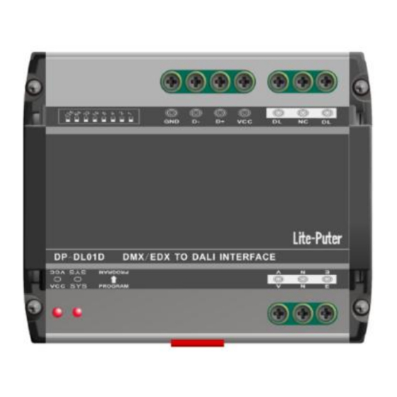
Page 4: Function
6. EDX/DMX-512 port 7. DALI port 1.4 About EDX/DMX-512 Wiring The digital signal wiring is basically the same as RS-485 wiring. If you are not familiar with RS-485 wiring, please check EDX/DMX-512 wiring guide on Lite-Puter’s website: http://www.liteputer.com.tw/tech_guide.asp DP-DL01D [EUM-E]... -
Page 5: System Diagram
1.5 System Diagram 1.5.1 EDX to DALI System By Ethernet (DP-107E or DP-104) DP-DL01D [EUM-E]... - Page 6 By USB (Only Applicable For DP-107E) DP-DL01D [EUM-E]...
-
Page 7: Dmx-512 To Dali System
1.5.2 DMX-512 to DALI System DP-DL01D [EUM-E]... -
Page 8: Operation
The number configuration is based on BCD code. Each switch on the 10 digit DIP switch represents as following figure. Examples: ID number is 01 (1) ID number is 06 (2+4) ID number is 11 (1 + 2 + 8) DP-DL01D [EUM-E]... -
Page 9: Edx To Dali Gui
3 EDX to DALI GUI “EDX to DALI” is an application to configure DP-DL01D. An EDX to Ethernet interface (PL-DP106E or DP-104E) is required to make “EDX to DALI” communicate with DP-DL01D. Please refer the previous EDX to DALI wiring diagram. - Page 10 Click “Select” button in the interface list to connect to the network interface. DP-DL01D [EUM-E]...
-
Page 11: Connect By Using Usb Cable (Only Applicable To Dp-107E)
3.2.1 Connect by Using USB Cable (Only Applicable to DP-107E) It is also possible to use USB port of DP-107E to configure DP-DL01D. Simply connect DP-107E’s USB to the PC, and run EDX2DALI GUI. Click “Connect” in “Configure by USB to EDX Interface”. -
Page 12: Id Number Of Dp-Dl01D
3.3 ID Number of DP-DL01D Make sure that you select correct ID number of DP-DL01D in “EDX to DALI” GUI. 3.4 Search DALI Devices 1. Click “DALI Setting” tab 2. Click “Search” If some DALI ballasts are previously addressed and some DALI ballasts are not addressed yet, please check “Expansion”... -
Page 13: Change Dali Address
You can use “Change DALI Address” function in “DALI Setting” tab to change the address after searching process. 3.4 Change DALI Address In “DALI Setting” tab, find “Change DALI Address” part. Select the DALI address and new DALI address and then click “Set” to change the address. DP-DL01D [EUM-E]... -
Page 14: Set Dali Device Parameters
2. DALI parameters can be read/write. Max Level: the maximum output level Min Level: the minimum output level Power On Level: the output level when power is supplied System Failure Level: the output level when system fails Actual Level: the real-time output level DP-DL01D [EUM-E]... - Page 15 Please refer the table below for real fade time. Fade Time 0,707 s 1.000 s 1,414 s 2.000 s 2,828 s 4.000 s 5,657 s 8.000 s 11,314 s 16.000 s 22,627 s 32.000 s 45,255 s 64.000 s 90.510 s DP-DL01D [EUM-E]...
-
Page 16: Dali Scenes
1. Click “DALI Scene Setting” tab 2. You can read/set DALI scenes by DALI address. 3. If you want to check the real-time output, please check “Real-Time Output”. The DALI output level will be controlled by the last changed slide bar. DP-DL01D [EUM-E]... -
Page 17: Dali Command Test
3.8 DALI Command Test 1. Click “DALI Command” tab 2. You can set DALI dimming level or recall DALI scenes. DP-DL01D [EUM-E]... -
Page 18: Edx To Dali Patch
2. You can patch/map DALI address to EDX zone/channel. Click “Save” to store the change. EX: DALI address 05 is patched to EDX zone1/channel 1: EDX’s zone1/ channel 1 command will control DALI address 05. EDX’s zone1 scene command will trigger the corresponding scene in DALI devices whose address is 05. DP-DL01D [EUM-E]... - Page 19 EX: DALI address 01 is patched to EDX zone 2/ channel 3 EDX’s zone2/ channel3 command will control DALI address 01. EDX’s zone2 scene command will trigger the corresponding scene in DALI devices whose address is 01. DP-DL01D [EUM-E]...
-
Page 20: Dmx-512 To Dali Patch
1. Click “DMX-512 to DALI” tab 2. Set corresponding DMX-512 to DALI address mapping and click “Save” to store the change. If DALI address 03 is patching to DMX-512 address 10, DMX-512’s channel 10 signal will control DALI ballast whose address is 03. DP-DL01D [EUM-E]... -
Page 21: Limited Warranty
1. Lite-Puter is only responsible for the product itself. 2. Lite-Puter warrants to repair any manufacturing defects within one year of distribution date. 3. Lite-Puter does not offer on-site service. Should a defect appear in Lite-Puter’s product, please deliver the product to local distributors or Taiwan Headquarters.
Need help?
Do you have a question about the DP-DL01D and is the answer not in the manual?
Questions and answers