Enviro HLF Installation Operation & Maintenance

Enviro HLF Installation Operation & Maintenance

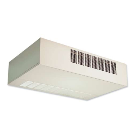
Horizontal, low profile fan coil

Advertisement

HORIZONTAL, LOW PROFILE FAN COILs
BY JOHNSON CONTROLS
Form ET115.24-NOM5 (908)
InstallatIon, operatIon & MaIntenance
New Release
MOdELs HLF / HLP / HLE
LD13884

Advertisement

Table of Contents
loading
Need help?

Need help?

Do you have a question about the HLF and is the answer not in the manual?

Questions and answers

Subscribe to Our Youtube Channel

Summary of Contents for Enviro HLF

  • Page 1 HORIZONTAL, LOW PROFILE FAN COILs BY JOHNSON CONTROLS Form ET115.24-NOM5 (908) InstallatIon, operatIon & MaIntenance New Release MOdELs HLF / HLP / HLE LD13884...
  • Page 2: Table Of Contents

    ForM Et115.24-noM5 (908) TABLE OF CONTENTS TABLE OF CONTENTS ..........................2 SAFETY SYMBOLS ..........................3 SAFETY CONSIDERATIONS .........................3 SECTION ONE - RECEIPT & INITIAL INSTALLATION ..............4 HL SERIES FEATURES..........................4 PREFACE ..............................4 UNPACKING & INSPECTION ........................5 HANDLING & INSTALLATION .......................5 Drain Pan ............................6 Coils ..............................6 HL SERIES DIMENSIONAL DATA ......................9 ARI STANDARD RATINGS........................10...
  • Page 3: Safety Symbols

    FORM ET115.24-NOM5 (908) sAFETY sYMBOLs The following symbols are used in this document to alert the reader to areas of potential hazard: DANGER indicates an imminently CAUTION identifies a hazard which hazardous situation which, if not could lead to damage to the machine, avoided, will result in death or serious damage to other equipment and/or injury.
  • Page 4: Section One - Receipt & Initial Installation

    Coils No attempt should be made to handle, PREFACE install, or service any unit without ENVIRO-TEC fan coils represent a prudent investment ® which can, with proper installation, operation, and following safe practices regarding regular maintenance, give trouble-free operation and mechanical equipment.
  • Page 5: Unpacking & Inspection

    FORM ET115.24-NOM5 (908) Never pressurize any equipment be- claim filed as before. In the event a claim for shipping yond specified operating pressures. damage is filed, the unit, shipping carton, and all packing must be retained for physical inspection by the freight Always pressure test with some inert carrier.
  • Page 6: Drain Pan

    ForM Et115.24-noM5 (908) Drain Pan During and after installation, special care must be taken to prevent foreign material such as paint, plaster, and drywall dust from being deposited in the drain pan or on the motor or blower wheels. Failure to do so may have serious adverse effects on unit operation and in the case of the motor and blower assembly, may result in immediate or premature failure.
  • Page 7 ForM Et115.24-noM5 (908) HL SERIES DIMENSIONAL DATA Drawings are subject to change without notice. Refer to www.enviro-tec.com for current submittal drawings. Model HLF (Free Return) lD13885 Johnson Controls...
  • Page 8 FORM ET115.24-NOM5 (908) HL sERIEs dIMENsIONAL dATA Drawings are subject to change without notice. Refer to www.enviro-tec.com for current submittal drawings. Model HLP (Plenum) LD13886 JOhNsON CONTROLs...
  • Page 9: Hl Series Dimensional Data

    ForM Et115.24-noM5 (908) HL SERIES DIMENSIONAL DATA Drawings are subject to change without notice. Refer to www.enviro-tec.com for current submittal drawings. Model HLE Horizontal Exposed Fan Coil Front Stamped Supply Grille, Bottom Stamped Return Grille NOTES: 1. All dimensions are Inches [millimeters]. All 1-1/2 dimensions ±1/4"...
  • Page 10: Ari Standard Ratings

    Model HLE tested HLF 50 1140 24000 19300 at 0.0" external static pres- HLF 60 1590 34000 26500 14.6 sure. Models HLF and HLP HLF 20 8500 6000 tested at 0.05" external static pressure. HLF 25 11600 8600 HLF 30 16900 12600 10.9...
  • Page 11: Auxiliary Drain Pans

    FORM ET115.24-NOM5 (908) HEATING CAPACITY 1 ROW 2 ROW 3 ROW 4 ROW UNIT UNIT NOM INAL TYPE SIZE (MBH) (MBH) (MBH) (MBH) 15.7 19.7 22.9 15.0 21.0 30.0 28.3 16.1 29.2 38.3 43.4 23.6 40.5 55.2 64.9 1000 28.7 53.7 73.7 86.5...
  • Page 12: Condensate Trap

    All ductwork and/or supply and return grilles should be installed in accordance with the project plans and specifications. If not included on the unit or furnished from the factory, ENVIRO-TEC supply and return ® grilles are available in a variety of types.
  • Page 13: Electrical Enclosure

    FORM ET115.24-NOM5 (908) Electrical Enclosure All field wiring should be done in accordance with governing codes and ordinances. Any modification of the unit wiring without factory authorization will result in voiding of all factory warranties and will nullify any agency listings. The manufacturer assumes no responsibility for any damages and/or injuries resulting from improperly field installed or wired components.
  • Page 14: Model Hlp Horizontal Fan Coil Optional Telescoping Bottom Panel Assembly, Typical Installation Instructions

    FORM ET115.24-NOM5 (908) MOdEL HLP HORIZONTAL FAN COIL Optional Telescoping Bottom Panel Assembly, Typical Installation Instructions Drawings are subject to change without notice. Refer to www.enviro-tec.com for current submittal drawings. TYPICAL INSTALLATION METHODS 2-1/4 [57] 10 [254] STANDARD FILTER FINISHED...
  • Page 15: Model Hlp Horizontal Fan Coil Optional Telescoping Bottom Panel Assembly

    FORM ET115.24-NOM5 (908) MOdEL HLP HORIZONTAL FAN COIL Optional Telescoping Bottom Panel Assembly Drawings are subject to change without notice. Refer to www.enviro-tec.com for current submittal drawings. 10 [254] CEILING LINE 5-1/4 [133] LOUVERED BOTTOM MIN. 15-1/4 PANEL, SEE NOTE 3 HNGD.
  • Page 16: Section Two - Start-Up

    FORM ET115.24-NOM5 (908) sECTION TWO - sTART-UP In the case of the manual air vent fitting, the screw GENERAL should be turned counterclockwise no more than 1-½ Before beginning any start-up operation, the start- turns to operate the air vent. Automatic air vents may up personnel should familiarize themselves with the be unscrewed one turn counterclockwise to speed initial unit, options and accessories, and control sequence to...
  • Page 17: Water System Balancing

    ForM Et115.24-noM5 (908) MOTOR AND FAN DATA 115 VOLTS 208/230 VOLTS 277 VOLTS UNIT MOTOR # OF SIZE SPEED H.P. FANS AMPS WATTS AMPS WATTS AMPS WATTS high (1) 1/30 Medium (1) 1/50 (1) 1/60 high (1) 1/15 Medium (1) 1/30 (1) 1/60 high (1) 1/10...
  • Page 18: Section Three - Normal Operation & Periodic Maintenance

    FORM ET115.24-NOM5 (908) sECTION THREE - NORMAL OPERATION & PERIOdIC MAINTENANCE GENERAL not be allowed to accumulate on the blower wheel or Each unit on a job will have its own unique operating housing. This can result in an unbalanced blower wheel environment and conditions that may dictate a condition that can damage a blower wheel or motor.
  • Page 19: Electrical Wiring & Controls

    1.56 [.14] 0.68 [.06] 0.56 [.05] 1.77 [.16] return grilles. [762 x 216 x 25] 4. Free area of ENVIRO - TEC ® Model (2) 20 x 8.5 x 1 2.08 [.19] 0.81 [.08] 0.80 [.07] 2.36 [.22] [508 x 216 x 25] HLE supply grille and minimum free (1) 20, (1) 30 x 8.5 x 1...
  • Page 20: Unit Weight Data (Lbs.)

    FORM ET115.24-NOM5 (908) UNIT WEIGHT dATA (lbs.) UNIT SIZE COMPONENT HLF BASE UNIT 40 [18] 51 [23] 59 [27] 69 [31] 91 [41] 111 [50] HLP BASE UNIT 45 [20] 56 [25] 65 [30] 80 [36] 103 [47] 123 [56]...
  • Page 21: Example Wiring Diagrams

    FORM ET115.24-NOM5 (908) EXAMPLE WIRING dIAGRAMs "Example Wiring Diagram - Typical 24 VAC Control Drawing (Refer to unit control enclosure for actual order-specific drawing)" 84-10-0615-REV05 JOhNsON CONTROLs...
  • Page 22 FORM ET115.24-NOM5 (908) EXAMPLE WIRING dIAGRAMs (Continued) "Example Wiring Diagram - Typical 24 VAC Control Drawing (Refer to unit control enclosure for actual order-specific drawing)" 84-10-0205-REV05 JOhNsON CONTROLs...
  • Page 23: Section Four - Inspection & Start-Up Checklist

    FORM ET115.24-NOM5 (908) sECTION FOUR - INsPECTION & sTART-UP CHECKLIsT RECEIVING & INsPECTION Unit Received Undamaged. Unit Received Complete As Ordered Unit Arrangement/hand Correct. Unit structural support Complete & Correct HANdLING & INsTALLATION Unit Mounted Level & square. Proper Access Provided For Unit & Accessories Proper Electrical service Provided.
  • Page 24 ©2008 Johnson Controls, Inc. P.O. Box 423, Milwaukee, WI 53203 www.johnson- Printed in UsA ET115.24-NOM5 (908) controls.com New Release...

This manual is also suitable for:

HlpHle

Table of Contents