Table of Contents
Advertisement
INSTALLATION, OPERATION & MAINTENANCE
INTRODUCTION
ENVIRO-TEC fan coils represent a prudent investment
which can, with proper installation, operation, and
regular maintenance, give trouble-free operation and
long service.
Your equipment is initially protected under the
manufacturer's standard warranty; however, this
warranty is provided under the condition that the steps
outlined in this manual for initial inspection, proper
installation, regular periodic maintenance, and everyday
operation of the equipment be followed in detail. This
HP SERIES FAN COILS
Supersedes ET115.24-NOM1 (0420)
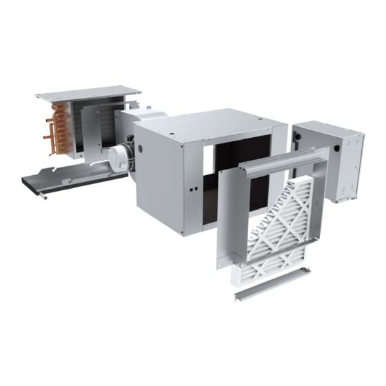
HP SERIES
HPP Plenum Return Shown
manual should be fully reviewed in advance of any
actual work being done on the equipment. Should
any questions arise, please contact your local Sales
Representative BEFORE proceeding.
The equipment covered by this manual is available with
a vast variety of options and accessories. Consult the
approved unit submittal, order acknowledgement, and
other manuals for details on the options and accessories
provided with the equipment on each project.
Form ET115.24-NOM1 (0520)
Advertisement
Table of Contents

Related Manuals for Enviro HP Series


Summary of Contents for Enviro HP Series
- Page 1 HPP Plenum Return Shown INTRODUCTION manual should be fully reviewed in advance of any ENVIRO-TEC fan coils represent a prudent investment actual work being done on the equipment. Should which can, with proper installation, operation, and any questions arise, please contact your local Sales regular maintenance, give trouble-free operation and Representative BEFORE proceeding.
-
Page 2: Table Of Contents
General........18 HP Series Coil Connection Sizes ....31 Cooling/Heating System . -
Page 3: Safety Symbols
Use flame and heat pro- connected prior to servicing. Electric tection barriers where needed. Have Heaters may start automatically, dis- fire extinguisher available and ready connect all power and control circuits for immediate use. prior to servicing to avoid burns. ENVIRO-TEC... -
Page 4: Section One - Receipt & Initial Installation
Return Authorization Number will be issued. Unauthorized return shipments of equipment and shipments not marked with an authorization number will be refused. In addition, the manufacturer will not accept any claims for unauthorized expenses. ENVIRO-TEC... -
Page 5: Handling & Installation
LEVEL plane. All units are supplied with hanging should be tested with water. holes for use with all thread rods. ALL hanging holes MUST be utilized when installing suspended units. ENVIRO-TEC... -
Page 6: Drain Pan & Auxiliary Drip Pan Removal
Which Secure The Auxiliary Drip Pan To The Main Unit Plenum. Step 2: Visually Locate Drain Pan Retention Studs. Step 2: Remove Both Retaining Screws And Carefully Remove The Auxiliary Drip Pan From The Unit. Step 3: Apply Slight Upward Pressure to Drain Pan. ENVIRO-TEC... -
Page 7: Cooling/Heating Medium Connections
1/8” per foot. A drain trap may be required by local codes and it is strongly recommended for odor containment. Condensate Trap “H” MUST BE AT LEAST 1 INCH PLUS CASING STATIC PRESSURE “X” MUST BE AT LEAST 1 INCH Trap detail for positive cabinet static pressure ENVIRO-TEC... -
Page 8: Plenum Box Service Panel
All ductwork and/or supply and return grilles should be installed in accordance with the project plans and specifications. If not included on the unit or furnished from the factory, ENVIRO-TEC supply and return grilles are available in a variety of types. ENVIRO-TEC... -
Page 9: Electrical Connections
The manufacturer assumes no be familiar with the wiring diagram and nameplate on responsibility for any damages and/or injuries resulting from improperly field installed or wired components. the unit BEFORE beginning any wiring. This unit is not acceptable for installation in hazardous/explosive ENVIRO-TEC... -
Page 10: Optional Telescoping Bottom Panel
Telescoping skirt and collar assembly must be field adjusted to assure a proper fit between filter frame and louvered inlet panel assembly. Refer to assembly submittal drawings for specific dimensions. AIR SYSTEM BALANCING ENVIRO-TEC... -
Page 11: Optional Telescoping Bottom Panel Assembly, Typical Installation Instructions
7. Telescoping skirt assembly must be field adjusted to assure close fit to louvered bottom panel. 8. Portions of the inlet louver not directly below unit inlet may require covering in the field on applications where infiltration of ceiling plenum air into space is undesired. ENVIRO-TEC... -
Page 12: Optional Telescoping Bottom Panel Dimensions
DO NOT SCALE DRAWING DO NOT SCALE DRAWING DIMENSIONS ARE IN INCHES UNLESS 9/10/15 PAGE 1 OF 1 PAGE 1 OF 1 82-80008 THIS DRAWING CONTAINS PROPRIETARY DATA. UNAUTHORIZED DISCLOSURE, ENVIRO-TEC OTHERWISE NOTED REPRODUCTION, OR USE IS STRICTLY PROHIBITED WITHOUT WRITTEN PERMISSION. -
Page 13: Service And Clearance Requirements
Package Catalog for valve package code details. Contact factory for details on valve packages using non-standard or customer furnished components. 5. Provide sufficient clearance to access electrical components and comply with all applicable codes and ordinances. UNCONTROLLED WHEN PRINTED TITLE: SUBMITTAL DRAWING ENVIRO-TEC MODEL HPP ALL DRAWINGS ARE SUBJECT TO CHANGE... - Page 14 DRAWING NO DO NOT SCALE DRAWING THIS DRAWING CONTAINS PROPRIETARY DATA. UNAUTHORIZED DISCLOSURE, REPRODUCTION, OR USE IS STRICTLY PROHIBITED WITHOUT WRITTEN PERMISSION. DIMENSIONS ARE IN INCH [MM] FORMAT 10/23/19 PAGE 1 OF 1 82-80056 +/- 1/8 [3] UNLESS OTHERWISE NOTED ENVIRO-TEC...
- Page 15 Package Catalog for valve package code details. Contact factory for details on valve packages using non-standard or customer furnished components. 5. Provide sufficient clearance to access electrical components and comply with all applicable codes and ordinances. UNCONTROLLED WHEN PRINTED ENVIRO-TEC TITLE: SUBMITTAL DRAWING MODEL HPP W / MIXING BOX...
- Page 16 Package Catalog for valve package code details. Contact factory for details on valve packages using non-standard or customer furnished components. 5. Provide sufficient clearance to access electrical components and comply with all applicable codes and ordinances. UNCONTROLLED WHEN PRINTED ENVIRO-TEC TITLE:...
- Page 17 Package Catalog for valve package code details. Contact factory for details on valve packages using non-standard or customer furnished components. 5. Provide sufficient clearance to access electrical components and comply with all applicable codes and ordinances. ENVIRO-TEC UNCONTROLLED WHEN PRINTED...
-
Page 18: Section Two - Start-Up
Inspect the entire system for potential air traps and vent those areas as required, independently. In addition, some systems may require repeated venting over a period of time to properly eliminate air from the system. ENVIRO-TEC... -
Page 19: Air System Balancing
Refer to the wiring diagram for each systems. unit for that unit’s individual operating characteristics. Motors are permanently lubricated, PSC or ECM type and do not require field lubrication. ENVIRO-TEC... -
Page 20: Motor & Fan Data
2. Motors nameplated for 208-230/1/60. Data is at 230 volts. (Quantity) ECM 3-SPD # OF UNIT SIZE FAN SPEED 3. ECM motors operated on 208/1/60 power result in reduced airflow. 3-Phase 3-Phase FANS ECM3 Neutral Neutral Current Current High (1) 1/6 ENVIRO-TEC (1) 1/3 (1) 1/3 Medium (1) 1/8... - Page 21 (2) 1/5 (2) 1/6 NOTES: 1. Motor electrical data is nameplate data. Actual data will vary with application. 2. Motors nameplated for 208-230/1/60. Data is at 230 volts. 3. ECM motors operated on 208/1/60 power result in reduced airflow. ENVIRO-TEC...
-
Page 22: Section Three - Inspection
Balance Air Systems as Required □ □ Record All Final Settings for Future Use Check Piping & Ductwork for Vibration □ □ Check All Dampers for Proper Operation Verify Proper Cooling Operation □ Reinstall All Covers & Access Panels ENVIRO-TEC... -
Page 23: Section Four - Normal Operation
Vacuuming should again follow this. Units provided with the proper type of air filters, replaced regularly, Example 2: Motor and Blower Aligned & may require periodic coil cleaning. Reassembled ENVIRO-TEC... -
Page 24: Unit Weight Data - 1/2" & 3/8" Coils
63 [28.7] 68 [30.9] 82 [37.1] 88 [39.9] 93 [42] NOTE: Unit weight data is in pounds [kilograms]. C:\Users\jklemmj\Desktop\HPFO Project 2019 - IN PROCESS\HPFO Coil Weights tables - 1.2 and 3.8 - IOM PLACEMENT uncontrolled when printed Coil Weights ENVIRO-TEC... -
Page 25: Electric Resistance Heater Assembly
MUST be corrected used during replacement. In some cases, the valve actuator may fail and usually can be replaced without removing valve body from piping. ENVIRO-TEC... -
Page 26: Electric Heat Rack Removal
Disconnect all power sources to avoid electrocution or shock injuries. The HP Series incorporates an innovative dropdown Electric Heat Rack Assembly, which allows for convenient manual reset limit switch access (if provided), heater element inspection, restring, or complete electric heat rack assembly replacement. -
Page 27: Drain
To replace the filter(s), turn the quick-release latches located at either side of the filter brackets counter- clockwise until the filter brackets can be removed. Slide out the used filter(s) and replace with the new one(s). Reattach the filter brackets by turning the quick-release latches clockwise. ENVIRO-TEC... -
Page 28: Face Area, Free Area And Filter Sizes
Number, which is provided by the factory. to the unit and could void all factory warranties. All equipment and components sold through ENVIRO- When ordering parts, the following information must be TEC are warranted under the same conditions as the supplied to ensure proper part identification: standard manufacturer’s warranty with the exception... -
Page 29: Optional Item Installation
Complete all assembly prior to mounting pump cover. g. Connect tubing. Once all of the connections are Illustration of Current Switch In Circuit made, reconnect the main power of the unit. Typical Current Switch Mounting Location ENVIRO-TEC... -
Page 30: Discharge Air Sensor
Test switch by lifting float with unit on. Unit should stop running if switch is correctly wired. Test switch sensitivity by filling pan and confirm switch stops unit before pan overflows. Diagram of Drain Pan Float Switch ENVIRO-TEC... -
Page 31: Hp Series Coil Connection Sizes
FORM ET115.24-NOM1 (0520) HP Series Coil Connection Sizes Drawings are representative and may vary depending on selected unit options. WATER & DX COIL CONNECTION SIZES UNIT SIZE TYPE # ROWS CONN. SIZE (OD) CW OR DX CW OR DX CW OR DX... -
Page 32: Section Five - Appendix
N-Series and F-Series TEC3000 – Installation Instructions Return Air Sensor (for operation with D-Series or P-Series) – Installation Instructions For the supplemental installation, operation and maintenance manuals listed above, please con- tact your local Sales Representative or visit www.enviro-tec.com/literature/iom. ENVIRO-TEC... - Page 33 FORM ET115.24-NOM1 (0520) NOTES ENVIRO-TEC...
- Page 34 ENVIRO-TEC is a registered trademark of Johnson Controls, Inc. in the United States of America and other countries. Other trademarks used herein may be trademarks or registered trademarks of other companies. Catalog: ET115.24-NOM1 (0520) Supersedes ET115.24-NOM1 (0420) © 2020 Johnson Controls, Inc. P.O. Box 423, Milwaukee, WI 53201 Printed in USA...
Need help?
Do you have a question about the HP Series and is the answer not in the manual?
Questions and answers