
Related Manuals for Enviro CFR


Summary of Contents for Enviro CFR
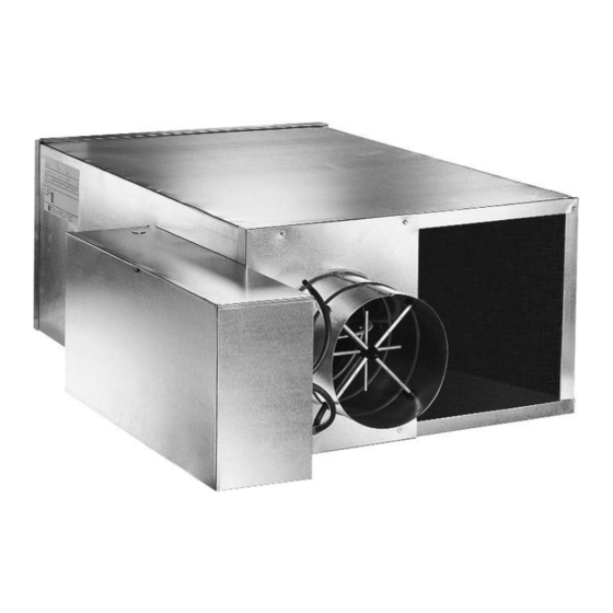
- Page 1 FAN POWERED VAV TERMINALS INSTALLATION, OPERATION & MAINTENANCE Supersedes: ET130.13-NOM3 (819) Form ET130.13-NOM3 (1219) MODELS CFR, CFRQ, CFL, VFR & VFL...
-
Page 2: Table Of Contents
Cleaning ............................12 Replacement ...........................12 Electric Heat ............................12 Replacement ...........................12 GENERAL TROUBLESHOOTING GUIDELINES ..................13 VALVE CALIBRATION CHARTS .......................14 FAN CFM CALIBRATION CURVES ......................15 TERMINAL UNIT WEIGHTS ........................16 FACTORY REPLACEMENT PARTS & WARRANTY .................17 COMPONENT INSTALLATION, OPERATION & MAINTENANCE APPENDIX .........18 ENVIRO-TEC... - Page 3 WARNING indicates a potentially NOTE is used to highlight additional hazardous situation which, if not information which may be helpful to avoided, could result in death or se- you. rious injury. ENVIRO-TEC...
-
Page 4: Safety Considerations
Check that rigging and lifting equip- handled. ment can safely support the equipment assembly and component weights. ENVIRO-TEC... -
Page 5: Inspection
1. Choose a dry storage site that is reasonably level received, contact your local Enviro -Tec representative immediately. and sturdy to prevent undue stress or permanent damage to the equipment. Set equipment off Do not use flow sensor, connecting ground if in moisture prone areas. -
Page 6: Sequence Of Operation
The fan delivers warm plenum air from will occur. the controlled space to the equipment’s outlet, which is mixed with the primary air prior to being delivered to the space. ENVIRO-TEC... -
Page 7: Clearances
Suspension devices are field supplied, Provide insulation around entire inlet collar (all the way sized and designed by others. ENVIRO-TEC will not to the equipment casing). accept responsibility for equipment mounting supports. -
Page 8: Coil Connections
0.1” wg. and 0.2” on 3/4hp and larger interior of the control enclosure box. (see fan curves located on the Enviro -Tec web site for specifics). All foreign materials should be removed Minimum circuit ampacity (MCA) designates the from the duct system. -
Page 9: Inspection & Start-Up Checklist
Balance Air Systems as Required □ □ Record All Final Settings for Future Use Check Piping & Ductwork for Vibration □ □ Verify Proper Cooling Operation Check All Dampers for Proper Operation □ Reinstall All Covers & Access Panels ENVIRO-TEC... -
Page 10: Series Flow, Psc Motor With Scr
Adjust and set the primary maximum airflow as necessary to meet job site requirements. See Table 2, Airflow vs. Velocity Pressure chart. This chart, with different inlet sizes, is also located on the side of the equip- ment. ENVIRO-TEC... -
Page 11: Maintenance
4. Replace access panels and restore electrical power to equipment. 5. Use caution to assure that any contaminated materi- al does not contact other areas of the equipment or building. Properly dispose of all contaminated materials. ENVIRO-TEC... -
Page 12: Cleaning
Should the secondary one-time trip limit switch trip, they will need to be replaced with a limit switch that has the same trip temperature as the one-time trip limit switch originally supplied with the ENVIRO-TEC... -
Page 13: General Troubleshooting Guidelines
Problems with Additional Stages Check contactors for open coil. Check for damaged elements. Incorrect CFM Check for blocked duct or location of heater. Incorrect Signal Applied Verify signal input. Heater with SSR Does Not Operate Interface Board Fuse Blown Replace fuse. ENVIRO-TEC... -
Page 14: Valve Calibration Charts
FORM ET130.13-NOM3 (1219) VALVE CALIBRATION CHARTS APPLICABLE CALIBRATION CHARTS ARE AFFIXED TO EACH UNIT AND MAY ALSO BE DOWNLOADED FROM THE ENVIRO-TEC WEBSITE AT WWW.ENVIRO-TEC.COM VALVE CALIBRATION CHART EXAMPLE ENVIRO-TEC... -
Page 15: Fan Cfm Calibration Curves
FORM ET130.13-NOM3 (1219) FAN CFM CALIBRATION CURVES APPLICABLE CALIBRATION CURVES ARE AFFIXED TO EACH UNIT AND MAY ALSO BE DOWNLOADED FROM THE ENVIRO-TEC WEBSITE AT WWW.ENVIRO-TEC.COM FAN CFM CALIBRATION CURVE EXAMPLE ENVIRO-TEC... -
Page 16: Terminal Unit Weights
FORM ET130.13-NOM3 (1219) TERMINAL UNIT WEIGHTS SERIES FLOW TERMINAL UNIT WEIGHTS CFR (22 GA) BASE UNIT WEIGHT ADDERS TO BASE UNIT WEIGHT WATER COIL SINGLE DOUBLE ELEC. SIZE WALL WALL HEAT 1 ROW 2 ROW 3 ROW 4 ROW 0506... -
Page 17: Factory Replacement Parts & Warranty
All equipment and components sold through ENVIRO- TEC are warranted under the same conditions as the standard manufacturer’s warranty with the exception... -
Page 18: Component Installation, Operation & Maintenance Appendix
N-Series, F-Series and V-Series TEC3000 Color – Installation Instructions Return Air Sensor (For Operation With D-Series or P-Series) – Installation Instructions For the supplemental installation, operation and maintenance manuals listed above, please con- tact your local Sales Representative or visit www.enviro-tec.com/literature/iom. ENVIRO-TEC... - Page 19 ENVIRO-TEC is a registered trademark of Johnson Controls, Inc. in the United States of America and other countries. Other trademarks used herein may be trademarks or registered trademarks of other companies. Catalog: ET130.13-NOM3 (1219) Supersedes ET130.13-NOM3 (819) © 2019 Johnson Controls, Inc. P.O. Box 423, Milwaukee, WI 53201 Printed in USA...
Need help?
Do you have a question about the CFR and is the answer not in the manual?
Questions and answers