
Related Manuals for Enviro VHC


Summary of Contents for Enviro VHC
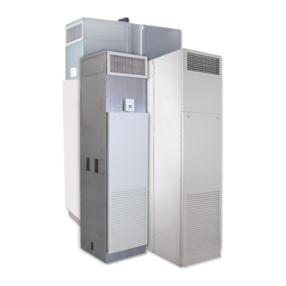
- Page 1 VERTICAL HI-RISE FAN COILS SERIES B INSTALLATION, OPERATION & MAINTENANCE Supersedes: ET115.24-NOM4 (317) Form ET115.24-NOM4 (819) MODELS VHC/VHS/VHM VERTICAL HI-RISE VHA/VHB TANDEM MASTER & TANDEM SLAVE...
- Page 2 All wiring must be in accordance with ENVIRO-TEC's published specifications and must be performed only by a qualified electrician. ENVIRO-TEC will NOT be responsible for damage/problems resulting from improper connections to the controls or application of improper control signals.
- Page 3 Updated manuals, if applicable, can be obtained by contacting the nearest ENVIRO- CHANGE BARS TEC Service office. Revisions made to this document are indicated with a...
- Page 4 Fan Relay Board II (FRBii) 2nd generation relay board, 24V Control Fan Relay Board II (FRBii) – Installation, Operation and Packages Maintenance ECM controller on variable speed ECM G3 PWM Board Fan Coil EC Motor IOM units NOTE: All documents downloadable at www.enviro-tec.com. ENVIRO-TEC...
- Page 5 Access Door Blower Shield (Optional) Deplugable Motor Hydronic Cooling/ Heating Coil Air Filter Outside Air Inlet (optional) Drain Pan With "P-Trap", Fixed Standard (Optional Slideout) Return Air/Access Panel (Optional, Shipped Loose) Note: Some optional items are included with other features. ENVIRO-TEC...
-
Page 6: Table Of Contents
Constant RPM EC Motor Driver Enable Jumper ................... 37 ECM 3-Speed Constant Torque Motor Troubleshooting Guide ..............38 Procedure for Checking ECM Constant Torque Wiring Harnesses ............39 ECM Constant Torque Motor Connections .................... 39 ECM Constant Torque Motor Specifications ..................40 ENVIRO-TEC... - Page 7 Replacement Parts ............................44 SECTION 4 - INSPECTION, INSTALLATION & START-UP CHECKLIST ............. 46 SECTION 5 - TROUBLESHOOTING ........................48 SECTION 6 - DIMENSIONAL DATA ........................51 Vertical Hi-Rise Tandem Units VHA/VHB Installation Instructions ........................75 Receipt & Initial Installation ........................75 Temperature ..............................79 ENVIRO-TEC...
- Page 8 FIGURE 40 - Model VH, Vertical High Rise Coil Unit, Aluminum Discharge Grille ..........60 FIGURE 41 - Model VHC/VHM/VHA Vertical High Rise Fan Coil Unit Arrangement Designations ......61 FIGURE 42 - Model VHC w/o Risers & VHS/VHB Vertical High Rise Fan Coil Units, Unit Arrangement Designations .............................62 FIGURE 43 - Model VH Vertical High Rise Coil Unit Outside Inlet Dimensions .............
- Page 9 FIGURE 45 - Assembly Instructions Return Panel with Latches, Quick Opening or Tamper Proof, Model VHC/VHM/VHS High Rise FCU .....................65 FIGURE 46 - Preparation Instructions for Model VHC/VHM Vertical High Rise FCU "Ship Loose" Riser Assemblies ..........................66 FIGURE 47 - Full Louvered Aluminum Return Air/Wall Panel Model VH Vertical High Rise Fan Coil Unit .... 67 FIGURE 48 - Model VH Vertical High Rise Fan Coil Unit Standard Surface Mount Wall Panel ......
- Page 10 FORM ET115.24-NOM4 (819) THIS PAGE INTENTIONALLY LEFT BLANK ENVIRO-TEC...
-
Page 11: Section 1 - Receipt & Installation
After determining the condition of the unit’s exterior, carefully remove each unit from the packaging and in- ENVIRO-TEC fan coils represent a prudent invest- spect for hidden damage. At this time, check to make ment which can, with proper installation, operation, sure that “ship loose”... -
Page 12: Handling & Installation
® erations. Solder joints with Sil-fos , phos-copper, or available to the unit. The electrical service to the unit similar high temperature alloy. Do not use soft solder. should be compared to the unit nameplate to verify ENVIRO-TEC... -
Page 13: Figure 1 - Flex Hose Connections
STEP 2. LOOSEN SCREW AT THE TOP OF VALVE. typical for riser shut off valve. STEP 3. TURN MEMORY STOP TO "EAR" ON VALVE BODY. STEP 4. TIGHTEN SCREW AT TOP OF VALVE. LD13871 FIGURE 2 - BALL VALVE WITH MEMORY STOP ENVIRO-TEC... -
Page 14: Flex Hose
Each unit is configured for a specific location in the building, and is marked with that location by room number, floor, riser number, or other identification as specified per order. LD13872 FIGURE 3 - FACTORY INSTALLED RISERS ENVIRO-TEC... -
Page 15: Factory Furnished, Field Installed Risers
FORM ET115.24-NOM4 (819) SECTION 1 - RECEIPT & INSTALLATION SHIPPING BRACKET, VITON O-RING REMOVE STRAP, P/N PR-07-0115 TYPICAL FIELD PIPING EXCEPT ENVIRO-PAC UNITS SHIPPED LOOSE RISERS HOSE CLAMP Master Unit Slave Unit HOSE CLAMP (Model VHM) (Model VHS) LD13866 LD13873... -
Page 16: Field Furnished And Installed Piping Or Risers
Due to building construction vari- CLAMP CLAMP LD13875 ations, some risers may require cutting or lengthening to correctly position the riser. Any field modifications FIGURE 8 - FIELD FURNISHED AND INSTALLED are the responsibility of the installer. RISERS MASTER/SLAVE ENVIRO-TEC... -
Page 17: Ductwork Connections
All penetrations for sult in injury, property damage, equipment piping and risers should be sealed with materials and damage, as well as void factory warranty. techniques suitable for all governing codes and ordi- nances. ENVIRO-TEC... -
Page 18: Field Reconfigurable Risers And Discharge Openings
SLIT CABINET factory for details. INSULATION LD13876 The manufacturer assumes no responsibility for unde- sirable system operation due to improper field design, equipment or component selection, and/or installation of ductwork, grilles, and other related components. FIGURE 9 - KNOCKOUT REMOVAL ENVIRO-TEC... -
Page 19: Wall Framing
These unit pairs must be installed according to the components. See Figure 10 on page 19 for critical procedure shown on Tandem Master & Tandem Slave penetration areas. Installation Instructions to maintain the fire rating for the unit. ENVIRO-TEC... -
Page 20: Outside Air Connection
The wing nuts are then tightened to lock the damper in place. ENVIRO-TEC... -
Page 21: Thermostats
The manufacturer assumes no responsibility for any installed on the thermostat mounting box, or discarded damages and/or injuries resulting from improperly as necessary. Unit surface mounted thermostats are field installed or wired components. provided with a plug assembly for easy connection. ENVIRO-TEC... - Page 22 SECTION 1 - RECEIPT & INSTALLATION FORM ET115.24-NOM4 (819) THIS PAGE INTENTIONALLY LEFT BLANK ENVIRO-TEC...
-
Page 23: Section 2 - Start-Up
Except as required during start-up and balancing operations, no fan coil units should be oper- ated without all the proper duct-work attached, supply and return grills in place, and all access doors and pan- ENVIRO-TEC... -
Page 24: Air System Balancing
The actual balancing technique may vary from OFF position, can create condensation on one system to another. the exterior of the cabinet. ENVIRO-TEC... -
Page 25: Fan Coil Ec Motor Control
• Digital multimeter capable of measuring 30 volts G3 PWM Board AC/DC and duty cycle The Enviro-Tec “Generation 3 PWM” (G3 PWM) • Insulated 1/8” flat bladed screwdriver board provides a pulse-width modulated (PWM) signal to the EC motor to control fan speed. The board is fac- •... -
Page 26: G3 Pwm Status Descriptions
3. Place Configuration Switch into Program Mode. LED returns to Always On. Use an insulated screwdriver to flip configuration switch #1 (closest to speed adjust potentiometer) to the ON position. See Figure 13 on page 26. ENVIRO-TEC... -
Page 27: Adjusting Ec Motor Speed
G3 PWM board. Separate instructions 10 VDC signal. are provided for Three Speed (adjustable) and 2 – 10 VDC Proportional motor control modes. For units with electric heat, fan speed must not be adjusted below 70 CFM/kW. ENVIRO-TEC... -
Page 28: Figure 16 - High Speed Adjust
Fan Calibra- tion Curve on unit. • STORE: Set switch 8 to Store (ON), wait one second, then to Set (OFF), to save the value. FIGURE 17 - MEDIUM SPEED ADJUST ENVIRO-TEC... -
Page 29: Vdc Proportional Motor Control
LOG programming mode (see Figure 20 on page 30). Switches to ON-ON-OFF-OFF-OFF-ON- OFF-OFF. • Set switch 1 to ON (Program). • Set switch 2 to ON (Analog). • Set switches 3 – 5 to OFF. • Set switch 6 to ON (2-10 V). ENVIRO-TEC... -
Page 30: Figure 20 - Mode To 2-10 Vdc Proportional Control
Set (OFF), to save the value. FIGURE 20 - MODE TO 2–10 VDC PROPORTIONAL CONTROL If adjusting Min/Max CFM values, con- tinue to step 3. Otherwise, skip to step 5. FIGURE 21 - MAX SPEED ADJUST ENVIRO-TEC... -
Page 31: Figure 22 - Min Speed Adjust
Min speed airflow. • STORE: Set switch 8 to Store (ON), wait one second, then to Set (OFF), to save the value. FIGURE 23 - NORMAL 2 – 10 VDC SPEED CONTROL FIGURE 22 - MIN SPEED ADJUST ENVIRO-TEC... -
Page 32: Ec Motor Troubleshooting Guidelines
No 24 VAC power Troubleshooting Guide. Verify float switch (if present) is made. Float switch tripped Verify motor rotates freely by hand with Motor seized blower disconnected. If not, replace motor. Damaged motor cable Cable is integral to motor, replace motor. ENVIRO-TEC... - Page 33 PWM board error or faulted 25. Verify all connections. Push reset button. Replace board if fault returns. Replace motor (Constant airflow or constant torque motors.) Replace driver Motor driver failure (Constant RPM motor.) Damaged motor cable Cable is integral to motor, replace motor. ENVIRO-TEC...
- Page 34 Verify that the pins in the Fixed Speed Motor runs in G3 PWM Program mode Loose pin in Fixed Speed Conn. Conn. harness (see location in Figure 12 but not in Run mode harness on page 25) are inserted fully. ENVIRO-TEC...
-
Page 35: Checking Ec Wire Harnesses
Before reconnecting power to unit, verify all harnesses are connected per diagram. Use light force when inserting meter probe into plug. Excess force will damage contacts. LD19309 FIGURE 25 - CONSTANT CFM/CONSTANT TORQUE EC MOTOR DRIVER ENVIRO-TEC... -
Page 36: Constant Rpm Ec Motors
MING CONNECTOR Chassis Ground DESCRIPTION AC Line (Line 1) +15V AC Line (Line 2, Neutral) Ground TABLE 7 - CON302, PWM SIGNAL INPUT DESCRIPTION Speed Control Input (H) Speed Control Input (L) Speed Control Input (H) Speed Control Input (L) ENVIRO-TEC... -
Page 37: Constant Rpm Ec Motor Driver Enable Jumper
TABLE 9 - CON202, FEEDBACK FROM EC MOTOR HALL SENSOR DESCRIPTION Ground Hall "W" Hall "V" Hall "U" LD19308 TABLE 10 - CON201, OUTPUT POWER TO MOTOR FIGURE 28 - CONSTANT RPM EC DRIVER EC DESCRIPTION MOTOR ENABLE CONNECTOR ENVIRO-TEC... -
Page 38: Ecm 3-Speed Constant Torque Motor Troubleshooting Guide
Motor runs in reverse or not Remove power from the unit. Replace Motor failure responding to speed adjustment motor. * - Fan Coil Relay Board ** - Verify wiring harnesses have no loose wires by gently pulling on each wire. ENVIRO-TEC... -
Page 39: Procedure For Checking Ecm Constant Torque Wiring Harnesses
TABLE 12 - THE ECM CONSTANT TORQUE MOTOR POWER WIRING HARNESS MOTOR WIRE COLOR FUNCTION FCRB CONNECTION CONNECTION Purple Signal Common 24 VAC - COM Line Voltage In - see Black Line Voltage equipment Green Ground N/A - Ground White Neutral P1 - L2/Neut ENVIRO-TEC... -
Page 40: Ecm Constant Torque Motor Specifications
6 mA Maximum current draw 12 mA TABLE 17 - GENERAL ECM CONSTANT TORQUE MOTOR SPECIFICATIONS MAX RATINGS @ NOM V, 1050 RPM MOTOR+CONTROL END TO END TORQUE WATTS IN WATTS IN WEIGHT (LBS) LENGTH (OZ-FT) (45C) (55C) 5.275” ENVIRO-TEC... - Page 41 FORM ET115.24-NOM4 (819) SECTION 2 - START-UP THIS PAGE INTENTIONALLY LEFT BLANK ENVIRO-TEC...
-
Page 42: Section 3 - Normal Operation & Periodic Maintenance
With proper unit application and operation, the high limit thermal cutout will not deactivate the heater. This device only operates when some problem exists and ANY condition that causes high limit cutout ENVIRO-TEC... -
Page 43: Electrical Wiring & Controls
More specific information regarding the use and operating characteristics of the standard controls offered by this manufacturer is contained in other manuals. ENVIRO-TEC... -
Page 44: Filters, Throwaway
12 months unless the component is furnished as warranty replacement. Parts furnished as warranty replacements are warranted for the remaining term of the original unit warranties. ENVIRO-TEC... - Page 45 FORM ET115.24-NOM4 (819) SECTION 3 - NORMAL OPERATION & PERIODIC MAINTENANCE THIS PAGE INTENTIONALLY LEFT BLANK ENVIRO-TEC...
-
Page 46: Section 4 - Inspection, Installation & Start-Up Checklist
Connect Incoming Power Service or Services Electrical Service of Correct Voltage and Ampacityto __________ _________ Support Unit Operating Loads __________ _________ All Field Wiring Installed With Code Compliance __________ _________ Check All Wiring For Secure Connections ENVIRO-TEC... - Page 47 __________ _________ Verify Proper Cooling Operation __________ _________ Verify Proper Heating Operation __________ _________ Reinstall All Covers & Access Panels SERVICE INTERVALS (record dates service performed): Filters: ______________________________________________________________________________________________ Drain Pan:___________________________________________________________________________________________ Motor/Blower: _________________________________________________________________________________________ Coil: _______________________________________________________________________________________________ Controls:____________________________________________________________________________________________ General: ____________________________________________________________________________________________ ENVIRO-TEC...
-
Page 48: Section 5 - Troubleshooting
Defective fan switch. simulate proper fan switch operation. Replace defective fan switch. Momentarily jumper “start/stop” relay to simulate proper Defective “start/stop” relay. relay operation. Replace defective “start/stop” relay. Verify proper fan switch operation and replace defective Defective fan motor. fan motor. ENVIRO-TEC... - Page 49 Replace thermostat as required. Defective control valve Manually place control valve in “open” position using lever on actuator housing. Replace actuator as required. actuator. Improper aquastat operation Verify proper aquastat position and operation. Replace on units so equipped. as required. ENVIRO-TEC...
- Page 50 Fan Relay Board II (FRBii) 2nd generation relay board, 24V Control Fan Relay Board II (FRBii) – Installation, Operation and Packages Maintenance ECM controller on variable speed ECM G3 PWM Board Fan Coil EC Motor IOM units NOTE: All documents downloadable at www.enviro-tec.com. ENVIRO-TEC...
-
Page 51: Section 6 - Dimensional Data
SECTION 6 - DIMENSIONAL DATA The drawings in this section are for reference only and should not be used for construction purposes. Reference submittal documents for most current version. 74-80080 FIGURE 33 - MODEL VHM, VERTICAL CONCEALED MASTER HIGH RISE, FCU, 88" CABINET ENVIRO-TEC... -
Page 52: Figure 34 - Model Vhs, Vertical Concealed Slave High Rise, Fcu, 88" Cabinet
SECTION 6 - DIMENSIONAL DATA FORM ET115.24-NOM4 (819) 74-80081 FIGURE 34 - MODEL VHS, VERTICAL CONCEALED SLAVE HIGH RISE, FCU, 88" CABINET ENVIRO-TEC... -
Page 53: Figure 35 - Model Vha/Vhb, Vertical Hi-Rise Tandem Fire Rated And Non-Fire Rated, Fcu Combinations, 88" Cabinets
FORM ET115.24-NOM4 (819) SECTION 6 - DIMENSIONAL DATA 74-80083 FIGURE 35 - MODEL VHA/VHB, VERTICAL HI-RISE TANDEM FIRE RATED AND NON-FIRE RATED, FCU COMBINATIONS, 88" CABINETS ENVIRO-TEC... - Page 54 SECTION 6 - DIMENSIONAL DATA FORM ET115.24-NOM4 (819) 74-80083 ENVIRO-TEC...
-
Page 55: Figure 36 - Model Vh, Vertical Concealed High Rise Fan Coil Unit With 79" Cabinet
FORM ET115.24-NOM4 (819) SECTION 6 - DIMENSIONAL DATA VH-031 FIGURE 36 - MODEL VH, VERTICAL CONCEALED HIGH RISE FAN COIL UNIT WITH 79" CABINET ENVIRO-TEC... -
Page 56: Figure 37 - Model Vhm, Vertical Concealed Master High Rise Fan Coil Unit With 79" Cabinet
SECTION 6 - DIMENSIONAL DATA FORM ET115.24-NOM4 (819) VH-032 FIGURE 37 - MODEL VHM, VERTICAL CONCEALED MASTER HIGH RISE FAN COIL UNIT WITH 79" CABINET ENVIRO-TEC... -
Page 57: Figure 38 - Model Vhs, Vertical Concealed Slave High Rise Fan Coil Unit With 79" Cabinet
FORM ET115.24-NOM4 (819) SECTION 6 - DIMENSIONAL DATA VH-033 FIGURE 38 - MODEL VHS, VERTICAL CONCEALED SLAVE HIGH RISE FAN COIL UNIT WITH 79" CABINET ENVIRO-TEC... -
Page 58: Figure 39 - Model Vha/Vhb, Vertical Hi-Rise Fire Rated And Non-Fire Rated Fcu Combinations, 79" Cabinets
See page 67 for dimensions. Refer to page 61, page 62, page 63 & page 64 for vertical Hi-rise Tandem Master & Tandem Slave configurations. VH-006-1 FIGURE 39 - MODEL VHA/VHB, VERTICAL HI-RISE FIRE RATED AND NON-FIRE RATED FCU COMBINATIONS, 79" CABINETS ENVIRO-TEC... - Page 59 (203) (305) 10 or 12 03 or 04 54-1/4 22-1/2 10 or 12 06 or 08 8 (203) 8 (203) (610) (1378) (572) (559) (203) (305) (203) (305) 10 or 12 10 or 12 See page 58 for notes. ENVIRO-TEC...
-
Page 60: Figure 40 - Model Vh, Vertical High Rise Coil Unit, Aluminum Discharge Grille
SECTION 6 - DIMENSIONAL DATA FORM ET115.24-NOM4 (819) VHC/VHS/VHM & VHA/VHB VHA/VHB 74-80020 FIGURE 40 - MODEL VH, VERTICAL HIGH RISE COIL UNIT, ALUMINUM DISCHARGE GRILLE ENVIRO-TEC... -
Page 61: Figure 41 - Model Vhc/Vhm/Vha Vertical High Rise Fan Coil Unit Arrangement Designations
SEE PAGE 63 FOR DETAILS. MODEL VHC UNITS SHOWN ABOVE WITH OPTIONAL RISER CHASE. RISER CHASE NOT AVAILABLE ON VHM UNITS. VHA UNITS MUST BE MATED TO VHB UNITS. VH-010 FIGURE 41 - MODEL VHC/VHM/VHA VERTICAL HIGH RISE FAN COIL UNIT ARRANGEMENT DESIGNATIONS ENVIRO-TEC... -
Page 62: Figure 42 - Model Vhc W/O Risers & Vhs/Vhb Vertical High Rise Fan Coil Units, Unit Arrangement Designations
SECTION 6 - DIMENSIONAL DATA FORM ET115.24-NOM4 (819) SEE PAGE 63 FOR DETAILS. VHC AND VHS VH-011 FIGURE 42 - MODEL VHC W/O RISERS & VHS/VHB VERTICAL HIGH RISE FAN COIL UNITS, UNIT ARRANGEMENT DESIGNATIONS ENVIRO-TEC... -
Page 63: Figure 43 - Model Vh Vertical High Rise Coil Unit Outside Inlet Dimensions
FORM ET115.24-NOM4 (819) SECTION 6 - DIMENSIONAL DATA VH-018 FIGURE 43 - MODEL VH VERTICAL HIGH RISE COIL UNIT OUTSIDE INLET DIMENSIONS ENVIRO-TEC... -
Page 64: Figure 44 - Model Vhm/Vha/Vhc Tandem Master & Tandem Slave Unit Configuration Fan Coil Unit
FIRE RATED TANDEM MASTER TANDEM MASTER & TANDEM SLAVE INSTALLATION & TANDEM SLAVE INSTRUCTIONS ON PAGES page 75 - page 77. NON-FIRE RATED VH-043 FIGURE 44 - MODEL VHM/VHA/VHC TANDEM MASTER & TANDEM SLAVE UNIT CONFIGURATION FAN COIL UNIT ENVIRO-TEC... -
Page 65: Figure 45 - Assembly Instructions Return Panel With Latches, Quick Opening Or Tamper Proof, Model Vhc/Vhm/Vhs High Rise Fcu
FORM ET115.24-NOM4 (819) SECTION 6 - DIMENSIONAL DATA VH-106 FIGURE 45 - ASSEMBLY INSTRUCTIONS RETURN PANEL WITH LATCHES, QUICK OPENING OR TAMPER PROOF, MODEL VHC/VHM/VHS HIGH RISE FCU ENVIRO-TEC... -
Page 66: Figure 46 - Preparation Instructions For Model Vhc/Vhm Vertical High Rise Fcu "Ship Loose" Riser Assemblies
SECTION 6 - DIMENSIONAL DATA FORM ET115.24-NOM4 (819) FIGURE 46 - PREPARATION INSTRUCTIONS FOR MODEL VHC/VHM VERTICAL HIGH RISE FCU "SHIP LOOSE" RISER ASSEMBLIES ENVIRO-TEC... -
Page 67: Figure 47 - Full Louvered Aluminum Return Air/Wall Panel Model Vh Vertical High Rise Fan Coil Unit
FORM ET115.24-NOM4 (819) SECTION 6 - DIMENSIONAL DATA VH-013 FIGURE 47 - FULL LOUVERED ALUMINUM RETURN AIR/WALL PANEL MODEL VH VERTICAL HIGH RISE FAN COIL UNIT ENVIRO-TEC... -
Page 68: Figure 48 - Model Vh Vertical High Rise Fan Coil Unit Standard Surface Mount Wall Panel
SECTION 6 - DIMENSIONAL DATA FORM ET115.24-NOM4 (819) 74-80084 FIGURE 48 - MODEL VH VERTICAL HIGH RISE FAN COIL UNIT STANDARD SURFACE MOUNT WALL PANEL ENVIRO-TEC... -
Page 69: Figure 49 - Recessed Wall Panel Model Vh Vertical High Rise Fan Coil Unit
FORM ET115.24-NOM4 (819) SECTION 6 - DIMENSIONAL DATA assembly instructions on page 65 for details. in Tandem Master & Tandem Slave pairs. VH-014 FIGURE 49 - RECESSED WALL PANEL MODEL VH VERTICAL HIGH RISE FAN COIL UNIT ENVIRO-TEC... -
Page 70: Figure 50 - Model Vh Vertical High Rise Fan Coil Unit Standard Return Wall Panel With Ada Thermostat
SECTION 6 - DIMENSIONAL DATA FORM ET115.24-NOM4 (819) assembly instructions on page for details. in Tandem Master & Tandem Slave pairs. VH-047 FIGURE 50 - MODEL VH VERTICAL HIGH RISE FAN COIL UNIT STANDARD RETURN WALL PANEL WITH ADA THERMOSTAT ENVIRO-TEC... -
Page 71: Table 18 - Discharge Register Performance Data, Vh Standard Fcu 88" Cabinet, Single And Double Supply
4. Drops are at 0° deflection. For 22.5° deflection, multiply by 0.85. For 45° deflection, multiply by 0.66. 5. Register Data is based on zero static and CRM show at high speed motor operation. 6. Data above does not reflect optional opposed blade damper information. ENVIRO-TEC... -
Page 72: Table 19 - Discharge Register Performance Data, Vh Standard Fcu 79" Cabinet, Single And Double Supply
4. Drops are at 0° deflection. For 22.5° deflection, multiply by 0.85. For 45° deflection, multiply by 0.66. 5. Register Data is based on zero static and CRM show at high speed motor operation. 6. Data above does not reflect optional opposed blade damper information. ENVIRO-TEC... -
Page 73: Figure 51 - Suggested Riser Floor Openings Vhc & Vhm
FORM ET115.24-NOM4 (819) SECTION 6 - DIMENSIONAL DATA VH-109 FIGURE 51 - SUGGESTED RISER FLOOR OPENINGS VHC & VHM ENVIRO-TEC... -
Page 74: Figure 52 - Riser Terminology, Model Vhc, Vhm, Vha Units
SECTION 6 - DIMENSIONAL DATA FORM ET115.24-NOM4 (819) VH-110 FIGURE 52 - RISER TERMINOLOGY, MODEL VHC, VHM, VHA UNITS ENVIRO-TEC... -
Page 75: Vertical Hi-Rise Tandem Units Vha/Vhb Installation Instructions
This publication details the installation requirements unit tag number against the tag label on the unit, for the Enviro-Pac dual unit configuration of the Verti- making sure that the unit assembly is installed cal High Rise, VH, unit assembly. Use of this docu-... -
Page 76: Figure 53 - Standard Installation
Type S screws spaced maximum 8” O.C. FIGURE 54 - ALTERNATE INSTALLATION 12. Risers shown in the standard location. Risers may be installed on the left or right side of Unit A. Wall construction should remain the same, regardless of riser location. ENVIRO-TEC... -
Page 77: Figure 55 - Mounting Details
FOR SUPPLY, RETURN, AND THERMOSTAT UNIT A UNIT B 7. INSTALL STUDS FROM TOP OF UNIT TO CEILING (4 CORNERS) SEE DETAIL A ABOVE 9. INSTALL GYPSUM BOARD TO WALLS SHEET 2 OF 2 PLAN VIEW PX-70-0001 LD13947 FIGURE 55 - MOUNTING DETAILS ENVIRO-TEC... - Page 78 SECTION 6 - DIMENSIONAL DATA FORM ET115.24-NOM4 (819) NOTES ENVIRO-TEC...
-
Page 79: Temperature
(°C), subtract 32° and multiply by 5/9 or 0.5556. Example: (45.0°F - 32°) x 0.5556 = 27.2°C To convert a temperature range (i.e., a range of 10°F) from Fahrenheit to Celsius, multiply by 5/9 or 0.5556. Example: 10.0°F range x 0.5556 = 5.6 °C range ENVIRO-TEC... - Page 80 ENVIRO-TEC is a registered trademark of Johnson Controls in the United States of America and other countries. Other trademarks used herein may be trademarks or registered trademarks of other companies. Catalog: ET115.24-NOM4 (819) Supersedes ET115.24-NOM4 (317) © 2019 Johnson Controls...
Need help?
Do you have a question about the VHC and is the answer not in the manual?
Questions and answers