
Subscribe to Our Youtube Channel
Related Manuals for Enviro VDD


Summary of Contents for Enviro VDD
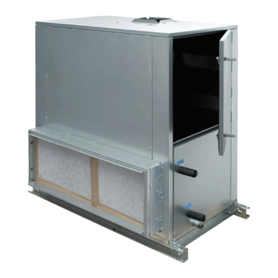
- Page 1 DIRECT DRIVE BLOWER-COIL UNITS INSTALLATION, OPERATION & MAINTENANCE Form ET115.24-NOM12 (718) Model VDD Model HDD...
-
Page 2: Table Of Contents
Electric Heat ......25 Section Six - Inspection & Start-Up Checklist Inspection & Start-up Checklist ....29 ENVIRO-TEC... -
Page 3: Safety Symbols
Use flame and heat Electric Heaters may start automatically, protection barriers where needed. disconnect all power and control circuits Have fire extinguisher available and prior to servicing to avoid burns. ready for immediate use. ENVIRO-TEC... -
Page 4: Section One - Receipt & Initial Installation
No attempt should be made to handle, PREFACE install, or service any unit without ENVIRO-TEC direct drive blower-coils represent a prudent investment which can, with proper installation, following safe practices regarding operation, and regular maintenance, give trouble-free mechanical equipment. -
Page 5: Unpacking & Inspection
“furnished only” items such as switches, thermostats, etc., temperatures. are accounted for. Any hidden damage should be recorded and immediately reported to the carrier and a claim must be filed. In the event a claim for shipping damage ENVIRO-TEC... -
Page 6: Unit Rigging And Placement
The unit’s drain pan is factory sloped toward the drain connection when the unit is installed level and plumb. Figure 1a: Side view Threaded rod Washer Unit Optional vibration isolator Figure 1b: Installation detail Figure 1a-1b: Typical ceiling installation ENVIRO-TEC... -
Page 7: Drain Pan
All installations should be made in compliance with all governing codes and ordinances. Compliance with all codes is the responsibility of the installing contractor. Figure 2b Figure 2a-2b: Drain pan access ENVIRO-TEC... -
Page 8: Cooling/Heating Medium Connections
If not included on the field piping techniques such as joint unit or furnished from the factory, ENVIRO-TEC supply compounds, soldering flux, and metal and return grilles are available in a variety of types. -
Page 9: Electrical Enclosure
All internal components should be checked for shipping damage. After installation and before energizing the unit, verify voltage and check that all electrical connections are tight. Electrical connections should be periodically checked for tightness. ENVIRO-TEC... -
Page 10: Condensate Drain And Traps
NO BASE RAIL WITH BASE RAIL WITH BASE RAIL AND HOUSEKEEPING PAD Housekeeping pad Depending on static Required to accommodate pressure, housekeeping trap height pad may not be needed for trap installation LD13929 Figure 4: Condensate drain and traps ENVIRO-TEC... -
Page 11: Service And Clearance Requirements
FORM ET115.24-NOM12 (718) SERVICE AND CLEARANCE REQUIREMENTS – MODEL HDD ENVIRO-TEC... - Page 12 FORM ET115.24-NOM12 (718) SERVICE AND CLEARANCE REQUIREMENTS – MODEL VDD ENVIRO-TEC...
-
Page 13: Clearance
FIELD WIRING ENVIRO-TEC. Violation will void warranty. Prior to installing any wiring, check the unit name plate for main power voltage, control voltage, transformer sizing and any fuse sizing. -
Page 14: Section Two - Start-Up
Strainers of which is provided on the back of this manual. Contact should be installed in the piping mains to prevent this the Sales Representative for additional copies of this material from entering the units during normal operation. sheet. ENVIRO-TEC... -
Page 15: Motor & Fan Data
Before and during water system balancing, conditions may exist which can result in noticeable water noise or undesired valve operation due to incorrect system pressures. After the entire system is balanced, these conditions will not exist on properly designed and balanced systems. ENVIRO-TEC... -
Page 16: Section Three - Normal Operation & Periodic Maintenance
Sales Representative. cleaner and a brush taking care not to dislodge the factory balancing weights on the blower wheel blades. Figure 5a Figure 5b Figure 5a-5b: Motor access ENVIRO-TEC... -
Page 17: Coil
High supply voltage also causes excessive amperage draw and may result in tripping of the circuit breaker or blowing of the fuses on the incoming power supply. Figure 6a Figure 6b Figure 6a-6b: Electric heater assembly ENVIRO-TEC... -
Page 18: Electrical Wiring & Controls
3. Coil and filter face areas are measured in square feet (1) 24.75 x 19.75 x 2 [629 x 502 x 51] [square meters]. (3) 24.75 x 19.75 x 2 8.4 [0.78] 10.2 [0.95] [629 x 502 x 51] 4. Cooling and heating coils have same face area. ENVIRO-TEC... -
Page 19: Drain
7. Test switch sensitivity. Fill pan and confirm that switch stops unit before pan overflows. 8. Follow all Lock-Out Tag-Out procedures when performing condensate float switch maintenance. Figure 8b: Drain pan float switch diagram ENVIRO-TEC... -
Page 20: Replacement Parts
When ordering parts, the following information must be supplied to ensure proper part identification: 1. Complete unit model number 2. Unit hand connection (right or left hand) while facing the direction of airflow at the inlet 3. Complete part description including any numbers. ENVIRO-TEC... -
Page 21: Section Four - Discrete Components
Ground the transformer according to local, national, and regional regulations. Failure to ground the transformer may result in electric shock and severe personal injury or death. The COM terminal on the secondary side of the transformer must be grounded per NEC requirements. ENVIRO-TEC... -
Page 22: Reference Wire Diagram
FORM ET115.24-NOM12 (718) REFERENCE WIRE DIAGRAM ENVIRO-TEC... -
Page 23: Inputs And Outputs
SPD1 (Low) on the Select PWM board. JUMPERS TABLE F.3 – JUMPER DESCRIPTION Jumper Name Description This jumper is installed between S1 and C when a float switch is not Float Switch Jumper installed. The jumper is removed when a float switch is installed. ENVIRO-TEC... -
Page 24: Checking Wire Harnesses
Before reconnecting power to unit, verify all harnesses • Unplug PWM wire harness from PWM board. are connected per diagram. • Verify continuity of wires, then reconnect. Use caution when inserting meter probe into plug. Excess force will damage contacts. ENVIRO-TEC... -
Page 25: Discrete Components
Electric heat signal is not Fan speed is not Verify that fan motor is running. A fan speed must be commanded to allow provided to commanded the electric heat contactor to energize on a call for heat. contactor ENVIRO-TEC... -
Page 26: Section Five - Troubleshooting
SECTION FIVE - TROUBLESHOOTING EC MOTOR TROUBLESHOOTING GUIDELINES For EC Motor troubleshooting questions please refer to the “EC Motor Solo, Select, and Sync PWM IOM, All Products” document found under the IOM Literature section of www.enviro-tec.com.. COOLING SYSTEM TROUBLESHOOTING GUIDELINES Problem... -
Page 27: Electric Heat
Use a volto-ohm meter to measure resistance Open or damaged heater elements across the electric heat power harness coming out of the heater section. If the meter measures an open or shorted circuit, replace with new elements. ENVIRO-TEC... - Page 28 [Solid state relay with state relay has DC control voltage at relay terminals. If proportional control] Solid control voltage at terminals and relay fails to pass voltage State Relay fault from safety contactor to heater, solid state relay is faulted. Replace relay. ENVIRO-TEC...
- Page 29 Verify operation of any control device such as drain pan Intermittent control device float switch, freeze stat, etc. When in doubt, jumper out and verify fan operation. Remove power from unit. Verify and/or tighten all wiring Loose wiring connections. ENVIRO-TEC...
- Page 30 If limit continues to Primary limit switch cycling trip, verify that heater is not overheating. Verify sufficient airflow and proper ductwork connections. NOTE: dual blower units have two heater racks and two primary limits. ENVIRO-TEC...
-
Page 31: Section Six - Inspection & Start-Up Checklist
Check piping & ductwork for vibration Check all dampers for proper operation Verify proper cooling operation Verify proper heating operation Reinstall all covers & access panels BLOWER/MOTOR Check blower wheel set screw tightness Check blower speed as necessary for balancing airflow ENVIRO-TEC... - Page 32 ENVIRO-TEC is a mark and/or registered mark. Unauthorized use is strictly prohibited. Catalog: ET115.24-NOM12 (718) © 2018 Johnson Controls www.enviro-tec.com...
Need help?
Do you have a question about the VDD and is the answer not in the manual?
Questions and answers