
Related Manuals for Enviro VL Series


Summary of Contents for Enviro VL Series
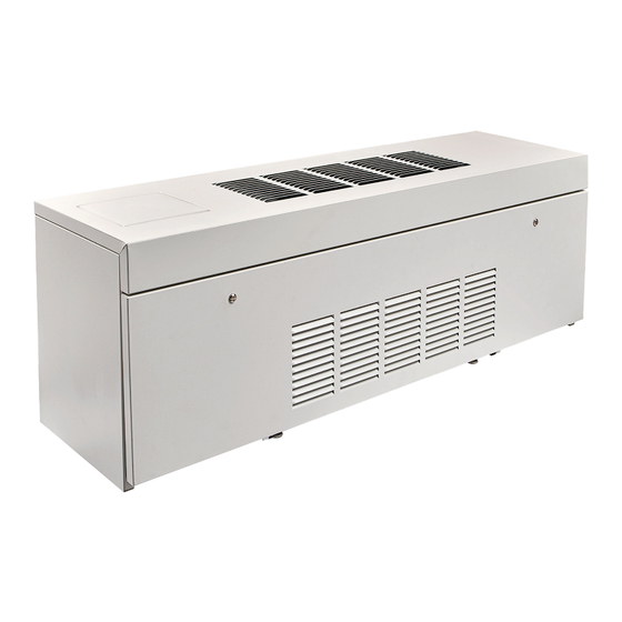
- Page 1 VL SERIES LOW HEIGHT VERTICAL FLOOR FAN COIL UNIT INSTALLATION, OPERATION & MAINTENANCE SUPERSEDES ET115.24-NOM3 (0923) Form ET115.24-NOM3 (0224) MODELS VLC/VLE...
-
Page 2: Table Of Contents
VLE SERIES ELECTRICAL AND PIPING SPACE REQUIREMENTS ..........18 VL SERIES COIL CONNECTION LOCATIONS ..................19 APPENDIX - COMPONENT INSTALLATION, OPERATION & MAINTENANCE MANUALS ...22 ALL DATA HEREIN IS SUBJECT TO CHANGE WITHOUT NOTICE Refer to www.enviro-tec.com for current catalog data and submittal drawings. ENVIRO-TEC... -
Page 3: Safety Symbols
Have connected prior to servicing. Electric fire extinguisher available and ready Heaters may start automatically; dis- for immediate use. connect all power and control circuits prior to servicing to avoid burns. ENVIRO-TEC... -
Page 4: Section 1 - Receipt And Initial Installation
VL SERIES FIG. 1 - VLE SERIES UNIT WITH FRONT PANEL HIDDEN, FILTER HIGHLIGHTED PREFACE ENVIRO-TEC fan coils represent a prudent investment, be fully reviewed in advance of any actual work being which can, with proper installation, operation, and done on the equipment. Should any questions arise,... -
Page 5: Unpacking & Inspection
Unauthorized return shipments of equipment switches and DDC controls are not factory tested. and shipments not marked with an authorization number will be refused. In addition, the manufacturer will not accept any claims for unauthorized expenses. ENVIRO-TEC... -
Page 6: Handling & Installation
All installations should be made in insure that the unit drain pan does not slope away from compliance with all governing codes and ordinances. the outlet connection. Compliance with all codes is the responsibility of the installing contractor. ENVIRO-TEC... -
Page 7: Cooling/Heating Medium Connections
All should be tested with water. documentation may be found at www.enviro-tec.com. All water coils must be protected from All accessory valve packages should be installed as freezing after initial filling with water. - Page 8 FORM ET115.24-NOM3 (0324) ENVIRO-TEC...
-
Page 9: Auxiliary Drain Pan Installation
3, to adjust the speed, simply move equipment or component selection, and/or installation the brown wire jumper to the de- of ductwork, grilles, and other related components. sired setting: high, medium, or low. ENVIRO-TEC... -
Page 10: Section Two - Start-Up
1-½ condition BEFORE beginning water system balancing turns to operate the air vent. Automatic air vents may operations. be unscrewed one turn counterclockwise to speed initial venting but should be screwed in for automatic venting after start-up operations. ENVIRO-TEC... -
Page 11: Water System Balancing
1/4 (0.18) ECM 3-SPD 1/4 (0.18) ECM 3-SPD 1/4 (0.18) ECM 3-SPD 1/4 (0.18) ECM 3-SPD 1/4 (0.18) ECM 3-SPD 1/4 (0.18) ECM 3-SPD 1/4 (0.18) NOTES: 1. Motor electrical data is nameplated data. Actual data will vary with application. ENVIRO-TEC... -
Page 12: Section Three - Normal Operation & Periodic Maintenance
Vacuuming should again follow this. Units provided with the proper type of air filters, replaced regularly, will require coil cleaning. FIG. 5 - AUTO-RESET AND MANUAL LIMIT SWITCH ENVIRO-TEC... -
Page 13: Fan Deck
Prior to use, check and seal all knockouts and unit penetrations; specifically around the coil and More specific information regarding the use and connections. operating characteristics of the standard controls offered by this manufacturer is contained in other manuals. ENVIRO-TEC... -
Page 14: Replacement Parts
1. Complete unit model number 2. Unit hand connection (right or left hand) while facing into the return air stream 3. Complete part description including any numbers ENVIRO-TEC... -
Page 15: Section Four - Inspection & Start-Up Checklist
Check and Seal All Unit Penetrations Check Piping & Ductwork for Vibration □ □ Record All Final Settings for Future Use Verify Proper Cooling Operation □ □ Check All Dampers for Proper Operation Reinstall All Covers & Access Panels ENVIRO-TEC... -
Page 16: Section Five - Unit Dimensions & Coil Connection Locations
VLC SERIES UNIT DIMENSIONS 7" 8 1/4" 4 7/8" 11 1/4" 7 5/8" 5 1/8" FILTER 3/4" 3/4" PIPE AUXILIARY DRAIN PAN CONNECTION (ALL VL SERIES UNITS) SUPPLY 1 1/4" 7 3/4" 1 1/4" PRIMARY DRAIN 11" 14 1/4" STD HT STD. -
Page 17: Vle Series Unit Dimensions
PAGE 1 OF 1 PAGE 1 OF 1 PAGE 1 OF 1 51-80051 51-80051 THIS DRAWING CONTAINS PROPRIETARY DATA. UNAUTHORIZED DISCLOSURE, +/- 1/8 [3] UNLESS OTHERWISE NOTED +/- 1/8 [3] UNLESS OTHERWISE NOTED REPRODUCTION, OR USE IS STRICTLY PROHIBITED WITHOUT WRITTEN PERMISSION. ENVIRO-TEC... -
Page 18: Vle Series Electrical And Piping Space Requirements
DO NOT SCALE DRAWING THIS DRAWING CONTAINS PROPRIETARY DATA. UNAUTHORIZED DISCLOSURE, DIMENSIONS ARE IN INCH [MM] FORMAT 06/29/23 PAGE 1 OF 1 51-80145 REPRODUCTION, OR USE IS STRICTLY PROHIBITED WITHOUT WRITTEN PERMISSION. +/- 1/8 [3] UNLESS OTHERWISE NOTED UNCONTROLLED WHEN PRINTED ENVIRO-TEC... -
Page 19: Vl Series Coil Connection Locations
FORM ET115.24-NOM3 (0324) VL SERIES COIL CONNECTION LOCATIONS VL SERIES COIL CONNECTION LOCATIONS FRONT FRONT REAR REAR BOTTOM BOTTOM LEFT HAND COIL RIGHT HAND COIL AIR TO FRONT AIR TO FRONT TITLE: MODEL VL FAN COIL UNIT SUBMITTAL DRAWING ALL DRAWINGS ARE SUBJECT TO CHANGE... - Page 20 FORM ET115.24-NOM3 (0324) VL SERIES VL SERIES COIL CONNECTION LOCATIONS (CONT’D) COIL CONNECTION LOCATIONS FRONT REAR REAR FRONT BOTTOM LEFT HAND COIL RIGHT HAND COIL BOTTOM AIR TO FRONT AIR TO FRONT TITLE: MODEL VL FAN COIL UNIT SUBMITTAL DRAWING...
- Page 21 FORM ET115.24-NOM3 (0324) VL SERIES VL SERIES COIL CONNECTION LOCATIONS (CONT’D) COIL CONNECTION LOCATIONS FRONT REAR REAR FRONT BOTTOM BOTTOM LEFT HAND COIL RIGHT HAND COIL AIR TO FRONT AIR TO FRONT TITLE: SUBMITTAL DRAWING MODEL VL FAN COIL UNIT...
-
Page 22: Appendix Component Installation, Operation & Maintenance Manuals
Digital Thermostat (D-Series) – Operating Manual Programmable Thermostat (P-Series) – Installation Guide Programmable Thermostat (P-Series) – Operating Manual N-Series and F-Series TEC3000 – Installation Instructions For the supplemental installation, operation and maintenance manuals listed above, please contact your local Sales Representative or visit www.enviro-tec.com/literature/iom. ENVIRO-TEC... - Page 23 FORM ET115.24-NOM3 (0324) NOTES ENVIRO-TEC...
- Page 24 ENVIRO-TEC is a registered trademark of Johnson Controls, Inc. in the United States of America and other countries. Other trademarks used herein may be trademarks or registered trademarks of other companies. Catalog: ET115.24-NOM3 (0324) Supersedes ET115.24-NOM3 (1123) © 2024 Johnson Controls, Inc. P.O. Box 423, Milwaukee, WI 53201...
Need help?
Do you have a question about the VL Series and is the answer not in the manual?
Questions and answers