
Related Manuals for B&C Technologies SI Series


Summary of Contents for B&C Technologies SI Series
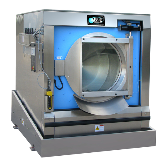
- Page 1 Washer-Extractor SI Series Installation and Operation Manual 9-Sep-2013 Revision 2.20...
-
Page 2: Table Of Contents
Contents 1 Model Identification 2 Important Instructions 2.1 Before Attempting Repairs ........2.2 Parts Ordering Information . - Page 3 5.2.6 Inverter Drive ........16 5.2.7 Machinery Misuse .
- Page 4 6.4.5 Partial Program ........38 6.4.6 Displaying the Current Program and Step .
-
Page 5: Model Identification
Chapter 1 Model Identification Information contained in this manual is for the following machines: SI-110 SI-135 SI-200 SI-275 SI-300 Refer to the SI Product Family chart on page 2 for details about the configuration and build of a particular machine. The Product Family Chart ”‘decodes”’ the model information as shown on the serial decal. - Page 6 Figure 1.1: SI Product Family...
-
Page 7: Important Instructions
Chapter 2 Important Instructions 2.1 Before Attempting Repairs Moving parts can cause serious injury or death. Before attempting repairs, follow proper shut- down procedures and remove power before commencement of service. Safety is of primary concern with any maintenance or repair operation. If you are in any way unsure of how to proceed with a repair or adjustment, consult this manual, a qualified mainte- nance technician, your local distributor, or the B&C Technologies Technical Service Department at 850-249-2222. -
Page 8: Parts Ordering Information
is available to answer any questions you may have about the operation and servicing of your machine. Please call with any questions or concerns about the operation of your machine. 2.2 Parts Ordering Information If you require literature or spare parts, please contact your local distributor. If a local distributor is unavailable, you may contact B&C Technologies directly at (850) 249-2222 for the name of your nearest parts dealer. -
Page 9: Key Symbols
2.3 Key Symbols Anyone operating or servicing this machine must follow the safety rules in this manual. Partic- ular attention must be paid to the DANGER, WARNING, and CAUTION blocks which appear throughout the manual and shown in figures 2.2 on page 5. Figure 2.2: Key Symbols 2.4 Safety Information Installation Notice: For personal safety and for proper operation, the machine must be grounded... -
Page 10: Installation And Operational Safety Instructions
Code, article 250-96. Elsewhere, the equipment should be grounded in accordance with ANSI/NFPA 70, or the Canadian Electrical Code, CSA C22.1. The ground connection must be to a proven earth ground, not to conduit or water pipes. 2.5 Installation and Operational Safety Instructions 1. -
Page 11: Introduction
More chemical connections are available as an option. The SI series can be provided with tilt devices that can tilt the machine one or both ways. This option provides for easy loading and unloading and saves hard labor. -
Page 12: Customer Service
3.1 Customer Service For technical assistance: In the United States Phone: (850)-249-2222 FAX: (850) 249-2226 e-mail: techsupport@bandctech.com Web: www.bandctech.com 3.2 Replacement Parts In the event that literature or replacement parts are required, contact the local distributor of the equipment, or contact B&C Technologies at the above phone numbers/internet addresses. 3.3 Theory of Operation The B&C SI models use a single-speed motor to drive the cylinder via V-belts in all speeds. - Page 13 the lifters are perforated on the top so that water can cascade over the goods and wet them quickly. This reduces water consumption as water is picked up at the cylinders lowest point and lifted and splashed over the goods at the highest point as the cylinder rotates. A stainless steel door is provided for loading and unloading.
-
Page 14: General Specifications
Chapter 4 General Specifications... - Page 15 Figure 4.1: SI Series General Specifications...
-
Page 16: Installation
Chapter 5 Installation 5.1 Receiving Inspection Upon receipt of the equipment, visually inspect for shipping damage and note any damage with the carrier before signing the shipping receipt, or advise the carrier of the damage as soon as it is noted. -
Page 17: Operator Safety
Before servicing any equipment, make certain it is disconnected from the electrical power source. Never allow operation of the machine when any safety device is malfunctioning. Never bypass safety devices. Never insert hands or objects into basket until it has completely stopped. Doing so could result in serious injury. -
Page 18: Safe Operation Environment
Never operate the machine with a bypassed or disconnected out-of-balance switch. Operating the machine with severe out-of-balance loads could result in personal injury and serious equipment damage. Do not place volatile or flammable fluids in any machine. Do not clean the ma- chine with volatile or flammable fluids such as acetone, lacquer thinners, enamel reducers, carbon tetrachloride, gasoline, benzene, naphtha, etc. -
Page 19: Machine Location
2. Air Pressure. Best performance will be realized if air is provided at a pressure of 80-100psi (5.4-6.7 bar). SI series machines will experience door seal and drain failure if compressed air service is interrupted. Regulators for the door seal and optional tilting should be set to a maximum of 15 PSI (1 bar) and 60 PSI (4 bar) respectively. -
Page 20: Inverter Drive
Always disconnect power and water supplies before a service technician performs any service procedure. Where applicable, steam and/or compressed air supplies should also be disconnected before service is performed. 5.2.6 Inverter Drive Machines equipped with AC drives require special attention with regard to the operating envi- ronment. -
Page 21: Dimensional Clearances
We reserve the right to make changes at any time without notice. Figure 5.1: Minimum Service Clearances Table 5.1: Minimum Service Clearnances UNITS UNITS SI Series SI Series Tilt Metric (A) Minimum rear clearance (B) Minimum clearance between machine and wall... -
Page 22: Mounting Bolt Installation
For a successful installation, a smooth level surface, so that the entire base of the machine is sup- ported and rests on the mounting surface, is absolutely requried. Note: Do not support the machine on only four points. Note: Freestanding washer-extractors do not require anchoring bolts unless specified by state or local codes. -
Page 23: Transportation Brackets
Remove both front and rear transportation brackets, as well as tilting transportation brackets. Fail- ure to remove shipping brackets before operation of the SI series will void your warranty. Inspect the machine carefully to ensure that all transportation brackets are removed. All transportation brackets are painted red for easy identification. -
Page 24: Electrical Installation
Figure 5.3: Typical Machinery Transportation Bracket Location conjunction with a sump pump should be used when gravity drainage is not possible, such as in below-ground-level installations. Before any deviation from specified installation procedures is attempted, the customer or installer should contact the manufacturer. Increasing the drain hose length, installing elbows, or causing bends will decrease drain flow rate and increase drain time, impairing machine performance. - Page 25 Figure 5.4: Drain System Information This machine must be installed, adjusted, and serviced by a qualified electrical maintenance personnel familiar with the construction and operation of this type of machinery. They must also be familiar with the potential hazards involved. If this warning is not observed, personal injury or equipment damage resulting in voiding the warranty may result.
-
Page 26: Water Connection
Never touch terminals or components of the AC drive unless power is discon- nected and the ”‘CHARGE”’ indicator LED is off. The AC drive retains potential deadly voltage for some time after the power is disconnected. There are no user- serviceable parts inside the AC drive. -
Page 27: Steam Connection
particles out of the solenoid valves. Hang the hoses in a large loop. Do not allow the hoses to kink. The water connections to the machine should be supplied by a hot and cold water line of least the sizes shown in table 5.4 on page 23. Refer to table 5.5 and 5.6 on page 23 for details on individual machine requirements. - Page 28 Never touch internal or external steam pipes, connections, or components. These surfaces can be extremely hot and will cause severe burns. The steam must be turned off and the pipe, connections, and components allowed to cool before the pipe can be touched. Table 5.7: Steam Service Consumption Data MODEL Units...
-
Page 29: Compressed Air Connection
5.10 Compressed Air Connection Best performance will be realized if air is provided at a pressure of 80-100psi (5.4-6.7 bar). SI Series machines will experience door seal and drain failure if compressed air service is interrupted. Ensure the provided air is filtered and dry. Wet and/or dirty air will cause rapid deterioration of internal components and void your warranty on these parts. -
Page 30: Chemical Connection
Figure 5.6: External Chemical Supply Connection Detail 5.11.1 Chemical Connection The supply compartment on the B&C SI models is located on the left front side of the machine. Supply cups can be accessed by opening the dispenser lid. The supply cups can be removed and filled as desired. -
Page 31: Chemical Signal Connections
Figure 5.7: SI Series external chemical injection points Attempting to obtain power from the machine terminals may damage the ma- chine circuit and/or the chemical injection system. Consult the chemical injec- tion supply system instructions for operational details. 5.11.2 Chemical Signal Connections Connection terminals are located in the rear control box for output signals to the chemicals injec- tion supply pump. -
Page 32: Chute Up Switch Installation
Figure 5.8: External Chemical Supply Terminal Block Detail inserted and tightened. Connect Hydraulic rams Temporarily install Chute Up Switch to operated the chute Apply electrical and air to machine Operate the chute, using the maintenance switch to make sure the safety locks properly en- gage freely Use the pendant to lower the chute, CHUTE ENABLE and LOAD, ensure safety locks disen- gage freely... - Page 33 Figure 5.9: Loading Chute Installation...
- Page 34 Figure 5.10: Loading Chute Up Switch Installation...
- Page 35 1. Check the proper supply for such characteristics as correct voltage, phase, and cycles to be certain they are correct for the machine. 2. Open manual shut-off water valves to the machine. 3. Press Emergency Stop button. 4. Apply power to the machine. 5.
-
Page 36: Operation
Chapter 6 Operation 6.1 Door Lock Operation The lock system uses a combination pushbutton / locking bar style mechanism which differenti- ates it from any other door lock in the industry. This design was developed as a result of analyzing the shortcomings of other door lock mechanisms on the market. -
Page 37: Periodic Maintenance
6.2 Machine Loading Proper loading of your SI series washer-extractor is a great factor in determining both the perfor- mance and longevity of your investment. Small loads are wasteful on many levels: 1. Small loads waste water, chemicals, electricity, and most expensively, time. Running your machine at lower than its rated capacity costs significant time and money. - Page 38 Table 6.1: Proper Load Sizing Dry Weight Capacity Model Capacity SI-110 110 lb 50 kg SI-135 135 lb 61 kg SI-200 200 lb 91 kg SI-275 275 lb 125 kg SI-300 300 lb 136 kg Figure 6.1: Chute Pendant Control...
-
Page 39: Wash Program Execution
Home Position - Machine is level, Chute is in the up position and Door is closed (this is the starting position for any operator function). Chute Enable - Tells the machine to lower the Chute when Load switch is selected Chute Disable - Chute will stay locked in the up position when Load/Unload is selected Load - When Chute Enable is selected, Starts the loading operation, door opens, Chute move down, Machine tilts back and start to jog automatically, and the water valve can be operated... - Page 40 Figure 6.2: Chute Maintenance Switch...
-
Page 41: End Step Condition: Level
PRWH1 EXECUT.? press START to execute the program, or RESET to return to program selection. While the program is executing, the display shows the current segment of the program, and the ending condition of the segment. See the following examples: 6.4.1 End Step Condition: Level If the end requirement of the segment (step) is a particular water level, the display will show: RINSE1 LVL=cm12... -
Page 42: Partial Program
SINGLE CYCLE Then quickly to: PREWASH=? Now, using the INC and DEC keys, you may choose the cycle you wish to run (PREWASH, WASH, RINSE, SPIN, UNROLL). When you have selected the cycle type, press ENTER and select the cycle number. -
Page 43: Halting A Program
6.4.9 Halting a Program At any time during the execution of the wash program, the running program can be terminated by pressing the STOP key. 6.4.10 Water Level Refresh While a program is running, if the water level drops to a level which is 3cm below the target level, cold water will automatically be added to replenish the level. - Page 44 temperatures, fills, drains, and levels dont meet programmed values. In the event of a program fault, the buzzer sounds and the display changes to show the fault: LEVEL FAULT Indicates a problem with the level sensing system. This could be a loose or cracked water level tube, the level sensor, or the level sensing circuit.
-
Page 45: Maintenance Alarm
OPEN DOOR Indicates the door is not closed properly. This fault disables the machine until cleared, and aborts a program if active. Press RESET to clear the fault. LEVEL=cm4 Indicates a water level of greater than 2cm a the onset of spin or at cycle end. The machine will resume the spin or unlock the door when the level falls below the threshold. -
Page 46: Maintenance
Chapter 7 Maintenance Routine maintenance maximizes operating efficiency and minimizes downtime. The maintenance procedures described below will prolong the life of the machine and help prevent accidents. Daily, weekly, monthly, and quarterly checklist are provided at the end of this section. Laminate the checklists to preserve them for repeated copying. -
Page 47: End Of Day
(b) Close the door without locking it and attempt to start the machine. The machine should not start with the door open. (c) Close and lock the door and start a cycle. Attempt to open the door while the cycle is in progress. - Page 48 1. Each month or after every 200 hours of operation, lubricate bearing and seals. See instruc- tions on the machine. (a) Use a premium grade lithium complex grease. Never mix two types of grease. (b) Pump the grease gun slowly, permitting only the following number of strokes: (c) Each bearing grease fitting, 2 strokes Do not pump the grease gun if grease comes out of the bearing housing.
-
Page 49: Quarterly
the adjustement screw located on the inboard side of the pump. See figure 7.3 on page 46. The hydraulic should fluid be changed every 2 years using hydraulic fluid type, HL, HM or HV type and Viscosity Grade 22(VG22). To change the fluid disconnect the two hydraulic hoses, the two DIN connectors, and four mounting screws. - Page 50 Figure 7.2: Hydraulic Pump Detail for models with Loading Chute Option Figure 7.3: Hydraulic Pump Adjustment...
- Page 51 Figure 7.4: Belt Tensioning and Alignment Table 7.1: Belt Tensioning Table BELT TENSION CHART Machine Model Deflection Force Applied Inch mm Lbs SI-110 0.25 SI-135 0.26 SI-200 0.24 SI-275 0.51 SI-300 0.51...
-
Page 52: Care Of Stainless Steel
Figure 7.5: Using a Belt Tensioning Tester 2. Tighten anchor bolts, if necessary. 3. Check all painted surfaces for bare metal (matching paint is available from the manufacturer.) (a) If bare metal is showing, paint with primer or solvent-based paint. (b) If rust appears, remove it with sand paper or chemical means. - Page 53 Figure 7.6: Steam Trap Service 1. Ordinary deposits if dirt and grease can be removed with detergent and water. The metal should be thoroughly rinsed and dried after washing. Periodic cleaning will help to maintain the bright surface appearance and prevent corrosion. 2.
-
Page 54: Service & Parts
Chapter 8 Service & Parts 8.1 Service Service must be performed by a qualified trained technician, service agency, or gas supplier. If service is required, contact the distributor from whom the equipment was purchased. If the dis- tributor cannot be contacted or is unknown, contact B&C Technologies for a distributor in your area. -
Page 55: Decommisioning
Chapter 9 Decommisioning In the event that the machine must be decommissioned, follow these steps: 1. Clean interior of machine, both basket and shell. 2. Disconnect electrical power. (a) Shut of main power supply at the breaker box or main control panel. (b) Do not attempt to disconnect power supply wires from power supply.
Need help?
Do you have a question about the SI Series and is the answer not in the manual?
Questions and answers