Table of Contents
Advertisement
Quick Links
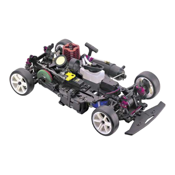
RTR INSTRUCTION MANUAL
1:10 SCALE NITRO POWERED TOURING CAR
OFNA RACING
22692 GRANITE WAY, STE. B
LAGUNA HILLS, CA. 92653
Tel: (949) 586-2910
SAFETY PRECAUTIONS
!
This radio control models is not a toy!
- First builders should seek advice from people having building experience in order
to assemble the model correctly and to produce it's performance to full extent.
- Assemble this kit only in places out of children's reach!
- Take enough safety precautions prior to operating this model. You are responsible
for this models assembly and safe operation!
- Always keep this instruction manual ready at hand for quick reference, even after
completing the assembly.
*SPECIFICATION ARE SUBJECT TO CHANGE WITHOUT NOTICE.
Advertisement
Table of Contents

Related Manuals for Ofna Racing nitro OB 4


Summary of Contents for Ofna Racing nitro OB 4
- Page 1 RTR INSTRUCTION MANUAL 1:10 SCALE NITRO POWERED TOURING CAR OFNA RACING 22692 GRANITE WAY, STE. B LAGUNA HILLS, CA. 92653 Tel: (949) 586-2910 SAFETY PRECAUTIONS This radio control models is not a toy! - First builders should seek advice from people having building experience in order to assemble the model correctly and to produce it's performance to full extent.
- Page 2 REQUIRED FOR OPERATION THINGS NEED BESIDES THE KIT .12 OR .15 ENGINE Glow Plug Heat with Battery & Charger Glow Fuel # 10227..$$19.95 (please note OFNA Glow Heats available) Fuel Bottle # 10160 - large 16oz # 10161 - large Auto Stop # 10162 - small 8oz .12 RED HEAD ENGINE # 50121 12V Battery for Starter Box...
- Page 3 READ THIS BEFORE RUNNING Running a nitro kit is fun and easy, but to make this a safe rusting. • Clear oil and dirt from chassis with a degreaser. and good experience you must observe a few rules. This kit is extremely fast, easily over 40MPH, and can seriously Precautions injure someone if you are not careful.
-
Page 4: Bag
SHOCK ASSEMBLY 37751 2mm E-Ring * The c-ring must fit into Step 1 (1mm x1 Hole) the groove 37967 PARTS USED * Cut the piston from C-Ring the plastic parts tree. (1.2mm x2 Holes) 37070 37965 37967 37100 39020 37967 Shock Body, Fnt/Rr Washer Piston... - Page 5 FRONT DIFFERENTIAL ASSEMBLY FRONT GEAR DIFF IS LONGER/WIDER THAN REAR Step 4-5 *Snap E-Ring onto Diff. Cap Joint. 39431 PARTS USED Differential Cap Joint, Long 2mm E-Ring Notice indent gear pocket, 39432 not for o-ring 5x7x1mm 37773 37771 O-Ring 37773 Steel Ring Bevel Gear Steel Ring...
- Page 6 PARTS USED REAR DIFFERENTIAL ASSEMBLY 37774 M2x10 Screw Differential Cap Joint 37773 37772 37775 Steel Ring 37772 Bevel Gear 3mmx20mm Bevel Gear 39432 5x7x1mm O-Ring M2x10 Screw 2mm E-Ring 37773 37751 Steel Ring 2mm E-Ring 37771 Bevel Gear 37776 Diff Pulley 39402 Diff Pulley 37775...
- Page 7 ASSEMBLY OF THE FRONT ARM BLOCK 39050 Front Arm Block ( Right ) 39050 39458 Complete, Front Arm Block Front ball Diff. Assembly ( Left ) Important *Notice the position of OPTION PARTS: 39460 OPTION PARTS: 34961 - Rear Ball the differential.
-
Page 8: Steering Ball X4
PARTS USED ASSEMBLY OF THE FRONT KNUCKLE ARMS * Make steering ball move smooth. 39090 Front Knuckle Arm ( Left ) 39140 Steering Ball * "L" make for left-side. 39150 39140 39090 10mm Front Knuckle Arm Hex Screw Steering Ball ( Right) 39141 Steering... - Page 9 ASSEMBLY OF THE FRONT SUSPENSION ARM TO ARM BLOCK Assembly of the right and left-side are the same. 37360 4mm Ball Socket 37751 3 x 3mm Set Screw 39070 Upper Arm Shaft 38240 Lower Arm Shaft 37360 * Insert the drive shaft before assembly.
- Page 10 ASSEMBLY OF THE FRONT STABILIZER TO ARM BLOCK 39090 Caster Angle Adjuster use adjuster t o change the caster angle . 39417 Front Lower Arm Stiffener 3 x 15mm Screw 39060 Stabilizer Cam Adjuster 3 x 15mm Screw 39060 Stabilizer Cam Adjuster 3 x 15mm * Turn stabilizer balance adjuster to...
-
Page 11: Table Of Contents
ASSEMBLY OF THE FRONT SHOCK TOWER 3 x 10mm Tapping Screw 39422 Front Alum. Black Shock tower 3x10mm Tapping Screw 3x10mm Tapping Screw * Notice the front tower and rear tower are not the same. ASSEMBLY OF THE REAR WHEEL HUB * Make 2 rear wheel hubs for left and right hand- side. -
Page 12: 10 X 15Mm Ball Bearing
PARTS USED ASSEMBLY OF THE REAR HUBS INTO REAR ARMS Assembly of the right and left-side are the same. 3 x 8mm Set Screw 37751 39060 37360 Rear Lower * Use this hole for 3 x8mm 37360 Ball & Scoket Set Screw 37360 4mm Ball Socket... - Page 13 PARTS USED ASSEMBLY REAR BLOCK COVER AND REAR LOWER ARMS 3 x 10mm Tapping Screw 39319 150 Belt (Rear) 3 x 10mm Tapping Screw 3 x 10mm Tapping Screw OPTION PARTS: 39468 Alum. Rear Block 39414 Rear Block Cover Cover ( Bigger ) * Insert rear belt before assembly.
- Page 14 ASSEMBLY OF THE FRONT STABILIZER 39060 PARTS USED Stabilizer Ball 3 x 3mm * Insert F-09B as shown. Set Screw 38090 1.6 x 35mm 3 x 3mm Stabilizer Set Screw 38090 1.6 x 35mm Stabilizer 3 x 3mm Set Screw 39060 Stabilizer Mount 39060...
- Page 15 ASSEMBLY OF THE REAR UPPER ROD 37381 37380 6mm Ball ( Make two rods for left and right hand side. ) 37380 Plastic Ball End Ball 37210 ( Long) 37380 37381 Turnbuckle Ball Plastic Ball End 37210 37210 ( Long) 3 x 15 3 x 15mm Turnbuckle...
- Page 16 OPTION PARTS: 37943 ASSEMBLY OF THE MAIN SHAFT Alum. Pulley Mount 37430 5 x 11mm 37400 2 x 8.8 Ball Bearing 39451 38055 2 Speed Brake Disc Main Shaft Mount 37400 Use the LONGER Disc Mount found in bag #5 or plastic tree #39415.
- Page 17 ASSEMBLY OF THE MAIN SHAFT ONTO * Insert the 2x8.8 pin into shaft OPTION PARTS: 37943 and keep the pin in the center of CHASSIS Alum.15T 37400 the pulley. Pulley Figure not shown in Dual 2 x 8.8 Brake OFNA configuration! OPTION PARTS: 39464 Alum.
- Page 18 ASSEMBLY OF THE TWO SPEED GEARS (45T OLIVE GREEN/41T PINK RATIO IS FOR SHORT TRACK RACING) 35952 35933 2.6 X 4mm 2.6 X 4mm Spur Gear Flat Head Flat Head ( Green) Screw Screw 35937 2nd Gear Carrier ( Ball Bearing ) 35936 1st Gear Carrier (One-Way)
-
Page 19: Ball Bearing X2
ASSEMBLY OF THE MIDDLE SHAFT 4mm E-Ring 2 x 8.8mm 4mm E-Ring 39409 Mid Shaft Pulley Washer 38050 Pulley Mount 37751 37660 15T Pulley 4 mm E-Ring *Take the pulley washer from K-15 plastic tree. 37430 5 x 11mm 39413 Ball Bearing Mid Shaft 37430... - Page 20 ASSEMBLY OF THE MIDDLE BELT E-Ring * Take the 17T pulley washer from 37661 plastic tree. 37400 2 x 8.8 37661 Pulley Washer 38050 Pulley Mount 37661 17T Pulley * Do not use the 16 tooth pulley here. 37400 2 x 8.8mm 37751 4 mm E-Ring OPTION PARTS: 37943...
- Page 21 ASSEMBLY OF THE MIDDLE TENSIONER ONTO CHASSIS 4 mm E-Ring E-Ring 3 x 3mm Set Screw E-Ring 35958 5 X 8 X 2mm Ball Bearing ASSEMBLY OF THE BATTERY HOLDER AND RECEIVER OPTIONAL FLAT PACK BATTERY HOLDER 37710 Body Clips 37710 Body Clips 39416...
- Page 22 ASSEMBLY OF THE RECEIVER 39415 Receiver Holder * Tighten the cable tie and cut off the excess. Antenna Wire Cable Tie 37420 Double-Sided Tape Receiver ASSEMBLY OF THE FRONT STEERING SERVO 10273Servo Mount 39423 (Black) 10273 Alum. Servo Mount Radio Tray 39414 Servo Washer 39414...
- Page 23 OPTIONAL ASSEMBLY OF THE FLAT BATTERY PACK 10273 Servo Mount 10273 Servo Mount 39423 Radio Tray, Black Alum. 3 x 10mm Tapping Screw 3 x 10mm Tapping Screw 39414 Servo Washer 39414 Servo Washer 3 x 10mm Tapping Screw Throttle Servo 3 x 10mm Tapping Screw 3 x 10mm...
- Page 24 ASSEMBLY OF THE SERVO AND STEERING ROD 37650 Ball End Steering Servo Rod 39419 (Righthand-Side) (Long) Servo Saver 3 x55mm Adapter Turnbuckle ( For: KO,Futaba,JR) 37650 Ball End 37360 Ball & Socket * Choose the correct servo saver 37650 adapter for you servo. Steering Servo Rod (Lefthand-Side) (Short) Ball End...
- Page 25 PARTS USED 36 36 ASSEMBLY OF THE CLUTCH 12-15 Class Side Exhaust Engine 59020 Pilot Shaft 3 x 5mm Screw 59021 3 shoes flywheel 10010 Clutch Shoes 5 x 10mm Ballbearing * Shoes are trailing. 5 x 8mm Ballbearing 59020 Pilot Shaft 10100 Clutch Spring...
- Page 26 38 38 ASSEMBLY OF THE MANIFOLD POWER PLANT MODULE 37935 Manifold, 16Dia., silver 37949 Manifold, 14Dia., black 38161 Muffler Gasket 38161 3 x30mm 3 x 30mm Screw Screw 30171 39 39 ASSEMBLY OF THE RADIO TRAY ONTO CHASSIS Brake Lever 3x3mm Set Screw 3x10mm...
- Page 27 40 40 ASSEMBLY OF THE ENGINE ONTO CHASSIS Note Book Paper 3 x 10mm Screw *Use note book paper to set gear backlash between spur gear and clutch bell gear. If the space is not correct the spur gear will be damaged. *Loosen or tighten 3 x10mm screw to adjust the mesh of the spur gear and clutch bell.
- Page 28 42 42 ASSEMBLY OF THE BRAKE LEVER * Use the screw provided with your radio. 3x3mm Set Screw * Align the servo horn and servo lever to 90 degree. * Keep 2mm distance between alum. stopper and brake lever. 43 43 CHECKING ENGINE THROTTLE FOR ROTARY CARBURETOR BRAKING NEUTRAL...
- Page 29 PARTS USED 44 44 ASSEMBLY OF THE THROTTLE LINKAGE ( For slide carburetor.) (Step 1.) 10300 3 x 3mm Set Screw Alum Stopper 2x10mm Screw 3 x 3mm Set Screw Throttle Spring 3 x 3mm 30530 Set Screw Throttle Ball Joint 10300 Alum Stopper...
- Page 30 46 46 ASSEMBLY OF THE MUFFLER 47 47 INSTALLATION OF AIR FILTER 10079 39474 Pressure Nipple Air Filter, refills 39473 Holder with foam disc. Strap Cable Tie Cable Tie 38163 * Insert air filter Silicon Tube into air filter holder * Apply filter oil to disc before using.
- Page 31 49 49 INSTALLATION OF THE SHOCK ABSORBER Assembly of the right and lefthand side ( Front and Rear ) are the same. * Take 2mm plastic washer from shock plastic parts. * Take 2mm plastic washer from shock plastic parts. 3 x 10mm Screw Plastic Washer...
- Page 32 50 50 ASSEMBLY OF THE BODY POST - p/n 37968 3x10mm Tapping Screw 37968 Body Post (Front) * Use "D" for front (2 Pcs) and "E" for rear (2 Pcs). 37968 Body Holder 37968 Body Post (Rear) 3x10mm Tapping Screw 30410 Body Pins * Insert body pins into body holder...
- Page 33 51 51 ASSEMBLY OF THE WHEELS INTO WHEEL HUB ( FRONT ASSEMBLY ) 37390 2 x 10.8mm Driver Nut (Alum.) PARTS USED Nylon Nut 37390 2 x 10.8 Pin 10376 M4 Nylon Nut ( REAR ASSEMBLY ) 37390 2 x 10.8mm Driver Nut (Alum.) Nylon Nut...
- Page 34 INSTRUCTIONS #39450 2 SPEED TRANSMISSION The #39450 2 speed transmission allows the car to have more punch out of the corners and higher top speed. We offer many different pinion and spur gear combinations which can be used for different tracks. * Adjust the engine before adjusting the clutch shift timing.
- Page 35 39413 37968 MAIN SHAFT BLOCK PLASTIC PARTS BODY POST 39414 REAR BLOCK COVER PLASTIC PARTS 39416 37949 31890 PIPE BATTERY HOLDER, FLA T PACK OPTION MANIFOLD 39420 CHASSIS R/C TIPS R/C cars are fun to drive, but be aware that driving them in the wrong places can cause serious damage. Never drive near real cars, animals, or people that are unaware the R/C car is being driven.
- Page 36 PLASTICPARTS 39090 39141 FRONT KNUCKLE ARM x1 STEERING BALL WASHER and CASTER ADJUSTER x2 37100 SHOCK PLASTIC PARTS x4 (Right) (Left) 39100 REAR HUB x1 39050 SUSPENSION ARM and FRONT BLOCK and BELT TENSION x1 Front Belt Tension 37650 4MM BALL END x1 Short Adjuster Front...
- Page 37 SETTING GUIDE FRONT and REAR WIDTH SETTING Front Down Stop Adjust front 3 x 8mm set screw. (FRONT) (FRONT) A=A' is 0K 91MM 91MM 172MM Rear Down Stop Adjust rear 3 x 8mm set screw. (REAR) (REAR) 91MM 91MM B=B' is OK 172MM FRONT TOE- IN and TOE- OUT SETTING REAR TOE-IN and TOE-OUT SETTING...
- Page 38 SETTING GUIDE SHOCK ANGLE SETTING USE THESE SETTING TO TUNE YOU CAR (REAR) (FRONT) Firm Soft Soft Firm Firm front suspension, less steering. Firm rear suspension, over steering. Soft front suspension, more steering. Soft rear suspension, under steering. (HARDNESS OF SHOCK OIL) 2 SPEED GEAR RATIO COMBINATIONS SETTING GUIDE (2) The #39450 2-speed transmission allows the car to have more punch out of the corners and higher top speed.
- Page 39 SETUP SHEET TIRE(F) MOTOR: NAME/ DATE/ TIRE(R) Fuel: TEMP/ CIRCUIT/ FRONT and REAR WIDTH SETTING Front (REAR) (REAR) (FRONT) Rear Front Down Stop Rear Down Stop Front (FRONT) (REAR) Rear CAMBER ANGLE Front (REAR) (FRONT) Rear TOE IN and TOE OUT Front Neutral Position Toe-In...
- Page 40 SETUP SHEET TIRE(F) MOTOR: DATE/ CIRCUIT/ FUEL: TIRE(R) WET: TEMP/ Clutch Gear Spur Gear Front Center Rear GEAR RATIO Hardness of Differential BEST LAP Lap 1 " Lap 2 Lap3 Lap 4 Lap 5 Lap 6 Lap 7 Lap 8 Lap9 Lap10 Lap11...
- Page 41 ENGINE BREAK-IN AND TUNNING (BREAK-IN THE ENGINE BEFORE DRIVING THE CAR!) • Choose a wide clear outdoor location with low dirt and dust. • Set the car on box or holder with wheels off the ground. • Turn on radio and car. Make sure throttle is at idle position. •...
Need help?
Do you have a question about the nitro OB 4 and is the answer not in the manual?
Questions and answers