
Related Manuals for Ofna Racing PICCO OFF ROAD


Summary of Contents for Ofna Racing PICCO OFF ROAD
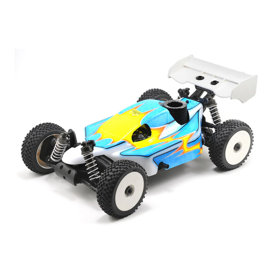
- Page 1 HI PerFORMANCE 1/8 OFF-ROAD NITRO BUGGY. Instruction manual OFNA 7 VANDERBILT, IRVINE, CA 92618 PH. (949) 586-2910...
- Page 2 RTR KITS - REQUIRED FOR OPERATION You will need to buy a few items to start the engine and run the car. THINGS NEEDED • Use 20% nitro CAR fuel. Do not use airplane or heli fuels, they will over heat engine. •...
- Page 3 MUST READ THIS BEFORE RUNNING Running a nitro kit is fun and easy, but to make this a safe • Clean oil and dirt from chassis with a degreaser like Simple Green. and good experience you must observe a few rules. This kit is extremely fast, easily over 40MPH, and can seriously Precautions injure someone if you are not careful.
- Page 4 THINGS REQUIRED FOR OPERATION OPTION THINGS NEED BESIDES THE KIT OPTION PART 3.5 cc (21 Class) ENGINE REAR EXHAUST OFNA/Picco Glow Plug Heat with Battery & Charger P7-EVO3 # 10227..$$19.95 (please note OFNA Glow Heats available) #51216 Bottle’s with spout # 10160 - large 500cc # 10161 - large 500 ccAuto Stop # 10162 - small 250cc...
- Page 5 PLASTIC PARTS FOR USE 40047 40046 RECEIVER BOX STONE GUARD 40020 36081 REAR LOWER ARM REAR UPRIGHT 36901 FRONT KNUCKLEARM ARM 40003 40017 DIFF. CASE GEAR BOX 40202 FRONT LOWER ARM...
- Page 6 PLASTIC PARTS FOR USE 40040 40027 CENTER DIFF. MOUNT WING STAY 40094 FRONT UPPER ARM 40018 / 40029 CHASSIS BRACE 40031 SERVO SAVER 16015 WING SYMBOL USED THROUGHOUT THE INSTRUCTION MANUAL Degrease With Do Not Ensure Free Contact Adhesive Tighten Ensure Parts Bag Used Motor Spray...
- Page 7 ASSEMBLY OF THE FRONT AND REAR DIFF. Builds two differentials for front and rear. Step 1 Step 2 40010 94034 4x4mm Set Screw ..x2 4x4 mm 40010 40009 40513 P6 O-Ring ..x4 40009 40006 40010 2.5x13.8mm Pin ..x4 49032 36053 36053 40006 40003...
- Page 8 ASSEMBLY OF THE CENTER DIFF. 3x12mm Step 1 Step 2 30776 30776 40513 Tighten ..x4 4x10mm Washer 30773 Tight the diff screws in this order. 94020 3x12mm Flat Head Hex Screw ..4 40011 30773 ..X2 Cross Pin Use 5000 weight diff. oil in the center.
- Page 9 ASSEMBLY OF THE FRONT LOWER ARMS Assembly for both right and left side. 90021 E-Ring ..x4 36870 4x10mm 4x10mm Set Screw ..x2 40202 40524 ASSEMBLY OF THE FRONT UPPER ARMS Assembly for both right and left side. 2.5mm 90020 2.5mm E-Ring ..x4 40094...
- Page 10 ASSEMBLY OF THE FRONT SUSPENSION ARMS Assembly for both right and left side. * Insert the drive shaft before assembling the knuckle arm. ASSEMBLY OF THE FRONT STABILIZER Assembly for both right and left side. 94035 3x8mm Set Screw ..x2 30403 6mm Ball ..x2...
- Page 11 ASSEMBLY OF THE SERVO SAVER Step 1 Step 2 40035 40037 40031 40031 Plastic Flange Bushing 40037 ..x2 40031 40031 49052 40031 40031 40033 40034 ASSEMBLY OF THE SERVO SAVER AND THE STEERING TIE-ROD 40027 Step 2 Step 1 3x10mm 94041 4x10mm Nylon Nut...
- Page 12 ASSEMBLY OF THE REAR GEAR CASE 4x12mm 5x4mm Step 1 Step 2 40017 94036 5x4mm Set Screw ..x1 94010 4x12mm Hex Screw ..x4 40027 4x12mm 30080 36053 36053 36053 8x16mm Ball Bearing 49012 ..x2 49049 40024 40024 40024 13x16x0.2mm Shim 4x16mm ..x2 4x45mm...
- Page 13 ASSEMBLY OF THE WING STAY Step 1 Step 2 94041 Nylon Nut ..x1 4x20mm 94042 4x16mm Nylon Nut ..x2 94011 4x16mm Hex Screw ..x2 Nylon Nut 3x25mm 4x16mm 94012 4x20mm Hex Screw ..x4 40018 94008 3x25mm Hex Screw ..x1 ASSEMBLY OF THE REAR LOWER ARMS Assembly for both right and left side.
- Page 14 ASSEMBLY OF THE REAR SUSPENSION ARMS Assembly for both right and left side. Nylon Nut Assembly of the rear upper arm. 94041 40065 Nylon Nut ..x4 36861 36850 36850 40065 7mm Ball ..x4 36850 94006 3x18mm ..x2 Hex Screw 3x18mm Nylon Nut 94008 3x25mm...
- Page 15 ASSEMBLY OF THE CENTER DIFF. MOUNT Step 1 Step 2 Step 3 40040 40042 40512 40040 40512 40042 ASSEMBLY OF THE BRAKE DISK INTO CENTER DIFF. MOUNT Step 1 Step 3 36661 36660 * Place the brake disc between the brake disc pads. Step 2 Brake * Remove the double-side...
- Page 16 ASSEMBL OF THE STONE GUARD Assembly for both right and left side. 40064 94003 40046 3x10mm Hex Screw ..x6 40046 3x10mm 3x10mm 3x10mm ASSEMBLY OF THE FRONT GEAR CASE ONTO CHASSIS 94039 4x10mm Flat Head Hex Screw ..x2 40013 94026 4x12mm Flat Head Hex Screw ..x2...
- Page 17 ASSEMBLY OF THE REAR GEAR CASE ONTO CHASSIS *Insert the drive shaft into 94026 the cap joint before assembly 4x12mm rear gear box onto chassis. 40028 Flat Head Hex Screw ..x2 94027 4x16mm Flat Head Hex Screw ..x4 4x16mm 4x12mm ASSEMBLY OF THE RADIO TRAY 3x12mm 3x10mm...
- Page 18 ASSEMBLY OF THE STEERING SERVO AND STEERING ROD *Approx. 18.5mm 30403 6mm Ball ..x2 * Use the screw 94003 provided with 3x10mm your servo . Hex Screw ..x1 30401 30661 30342 30403 30403 30401 3x10mm ASSEMBLY OF THE RADIO TRAY AND STICK PACK BATTERY Step 1 Step 2 40130...
- Page 19 ASSEMBLY OF THE FUEL TANK ONTO CHASSIS Step 1 Step 2 3x10mm 3x10mm Flat Head Hex Screw ..x2 3x10mm 3x10mm 40066 Hex Screw ..x2 40047 Do Not Over Tighten 3x10mm 40047 ASSEMBLY OF THE CLUTCH Step 1 Step 2 10010 38313 10040 *Fit the flywheel using a pair of the...
- Page 20 ASSEMBLY OF THE ENGINE ONTO CHASSIS Note book Paper. 10114 *Use note book paper to set gear backlash between spur gear and clutch bell gear, Engine Mount Screw applying pressure while retightening the ..x4 engine. *If the space is not correct the spur gear will be damaged.
- Page 21 ASSEMBLY OF THE THROTTLE LINKAGES INTO LEVER 3x3mm 94033 3x3mm ..x2 10300 10300 Set Screw Fuel Tube Snap On * Use the screw provided with your servo . 10769 ADJUSTING THE ENGINE CONTROL LINKAGES (Neutral) (Throttle High) (Brake) Approx. 0.5mm Idling adjusting Screw Approx.
- Page 22 *Assemble 2 for front ASSEMBLY OF THE FRONT SHOCKS CORRECT SHOCK ASSEMBLY Step 1 Step 2 Carefully screw the 40060 shock shaft into the 41006 bottom of the plastic Fit the o-ring into groove before 2.6x5mm ball and until the assembly distance between the 41008...
- Page 23 ASSEMBLY OF THE FRONT SHOCK ABSORBER 94041 Nylon Nut ..x2 94040 3x8mm Washer ..x2 40643 94007 3x20mm Hex Screw ..x2 3x8mm 3x20mm Assembly for both right and left side. ASSEMBLY OF THE REAR SHOCK ABSORBER 94041 Nylon Nut ..x2 94040 3x8mm Washer ..x2 40643...
- Page 24 ASSEMBLY OF THE WING 3x12mm 40027 40027 Body Reamer (Not included) 94041 16015 Nylon Nut ..x2 94004 3x12mm Hex Screw ..x2 Drill two 7mm holes for mounting. ASSEMBLY OF THE TIRES AND WHEELS Step 1 Step 2 Apply instant glue into the groove of the wheel. 81095 86056 86082...
- Page 25 ASSEMBLY OF THE BODY AND PAINTING Use a neutral detergent to Cut out the body as shown. remove any dirt and oil. Mask the windows from Apply internal color decals the inside with masking tape. from the inside and paint the body with polycarbonate spray paints.
- Page 26 MOUNTING BODY 31159 Body Clips 31159 Body Clips STARTING OF THE ENGINE How to start the engine: 12V Starter and Starter Glow Plug 1.2V Glow Plug Igniter (Not Included) Ring (Not Included) ( Not Included) 1. Turn on transmitter and then receiver. 2.
- Page 27 34952 Picco off-road parts list OFNA DESCRIPTION RETAIL OFNA DESCRIPTION RETAIL 10010 CLUCTH SHOES BLACK 3PCS 13.95 40028 DOG BONES, 93MM PAIR LX1 19.95 10040 3 PIN FLYWHEEL, .21 CORN TYPE 14.95 40029 BALL ENDS, PLASTIC, ANTI-ROLL 3.95 10060 MANIFOLD, ROUND EXHT, BLACK 25.95 40031 SERVO SAVER HORN 15.95...
- Page 30 SETTING GUIDE FRONT CAMBER ANGLE SETTING REAR CAMBER ANGLE SETTING Turnbuckle Positive Negative Positive Negative Place the model car on flat surface. Raise the chassis to it's maximum clearance before the wheels leave the ground. Adjust the length of the front and rear upper arms so that the wheels are right angle to the ground.
- Page 31 The registration card should be filled out and mailed to OFNA Racing within 10 days of purchase date. In the event that the kit is incomplete or component parts are broken due to error in manufacturer, contact your dealer from which you purchased the kit for replacement part or call OFNA at (949) 586-2910 for your nearest dealer location.
Need help?
Do you have a question about the PICCO OFF ROAD and is the answer not in the manual?
Questions and answers