
Related Manuals for Ofna Racing Ultra II


Summary of Contents for Ofna Racing Ultra II
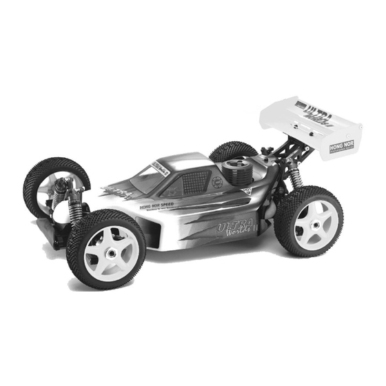
- Page 1 1/8 Scale Gas Powered Off-Road Buggy The body shown is slightly different in the U.S. kits PURE COMPETITION... INSTRUCTION MANUAL OFNA Racing 22692 Granite Way, Ste. B Laguna Hills, Ca. 92653 (949) 586-2910 Www.ofna.com...
-
Page 2: Required For Operation
REQUIRED FOR OPERATION THINGS NEED BESIDES THE KIT 3.5 cc (21 Class) ENGINE REAR EXHAUST Glow Plug Heat with Battery & Charger Glow Fuel # 10227..$$19.95 (please note OFNA Glow Heats available) Fuel Bottle # 10160 - large 16oz # 10161 - large AutoStop # 10162 - small 8oz 12V Battery for Starter Box (must have) - Page 3 PLASTIC PARTS USED #30010 #36020 Upper #30750 - Frt & Rr Cases #30770 Bevel Gear #30200 Center Diff Mounts Main Gear Box Arm, frt (K) « e ¤ W Â \ Á u #30760 - Center Case #36060 C Hubs (K) #36010 Lower arm, Rear (K) #36051 Knuckles, 8mm #36081 Rear Uprights...
-
Page 4: Shock Assembly
SHOCK ASSEMBLY 2.6mm Nut * Fit into groove. 2.6 x 5mm Oil Seal Washer Washer Washer Piston *Push Onto Shock Cylinder Option: Shock Cylinder #32203 Shock Shaft #32039 Dust Pusher #32237 O-ring Pistons (Yellow Rubber) O-Ring, rebuild * Assembly 4 pieces of the E-Ring shock Shaft . - Page 5 ASSEMBLY OF THE DIFFERENTIAL GEAR * Position the O-ring as shown. #31322 Diff. Case ( Front/Rear ) #31323 Diff. Case (Center ) #30779 2 x 12.8mm #30779 #30779 4 x 10mm 3 x 30mm 0.5 x 26mm Washer O-Ring Cap Screw #30770 Diff.
- Page 6 ASSEMBLY OF THE SPUR GEAR #31040 Steel Spur Gear #30111 * Notice the tapered holes 3 x 10mm are for the center diff. Only. Flat Head Screw & Nut Nylon Nut #31323 Diff Unit, Center, Complete #30760 Diff Case, Center 3 x 10 mm Flat Head #30111 Screw...
- Page 7 3 x 10mm ASSEMBLY OF THE CENTER DIFF. AND BRAKE CAM Tapping Screw 3 x 3mm Set Screw #30171 Brake Lever, Lower * Notice: The direction of the brake cam. #30210 #30220 Brake Cam Center Plate #30210 Brake Cam #30212 #30212 Bearing, Brake Cam Bearing, Brake Cam...
- Page 8 #30010 Main Gear Box * Make two gear boxes for front and rear. 4 x 20mm Flat Head GEAR Tapping Screw GREASE #30010 Main Gear Box 3 x 20mm Flat Head Tapping Screw ASSEMBLY OF THE FRONT SHOCK TOWER #36670 #36620 Alum.
- Page 9 ASSEMBLY OF PIVOT BALL TYPE (M STYLE) SUSPENSION #36904 #36903 #36905 14mm Alum. Nut x 4 13.8mm Steering Ball x 4 Plastic Washer & Arm Adjusters #36901 Ball Type Knuckle Arm ( Right ) ( Left ) #36900 Front Upper Arm #36890 Front Lower Arm #36902...
- Page 10 ASSEMBLY OF THE FRONT SUSPENSION ARMS, M STYLE Step 2 Assembly of the right and left hand side are the same. #36870 #36890 4x10mm Set Screw Front Lower Arm * A 4 x 10mm set screw is used to adjust the ride height. #36055 2.5 x 17mm * Approx 3mm.
- Page 11 ASSEMBLY OF THE FRONT SUSPENSION ARMS, M STYLE Step 4 * Cut the sharded area Assembly of the right and left hand side as shown. are the same. #30102 Front Body E-Ring 3 x 3mm Post Set Screw 3 x 3mm Set Screw 3 mm E-Ring 3 x 8mm 3x8mm...
- Page 12 ASSEMBLY OF THE FRONT SUSPENSION ARMS, K STYLE #36860 * Builds two front upper arms for left 5x40mm and right-side. . Turnbuckle #36690 Plastic, Arm Ball End 3 x 20mm Flat Head #36020 Tapping Screw Front, Upper Arms * If too tight, cut or sand to fit the shaded area as shown.
- Page 13 ASSEMBLY OF THE FRONT LOWER ARMS Assembly of the right and left hand side ONTO THE GEAR BOX, K STLYLE are the same. #36720 Lower Arms Stiffener (Alum.) E-Ring 4 x 10mm Tapping Screw 4 x 10mm Tapping Screw * Insert drive shaft before assembly.
- Page 14 ASSEMBLY OF THE #30401 Assembly of the right and left hand side are the same. STABILIZER ROD 6mm Plastic Stabilizer Ball End #30402 3 X 30mm 3 x 25mm Tie Rod Cap Screw #30401 #36610 6mm Plastic Spacer, Shock Support Stabilizer Ball End 3 x 15mm...
- Page 15 ASSEMBLY OF THE REAR SHOCK TOWER Assembly of the right and left hand side are the same. #36810 Rear Shock Tower 3 x 20mm Flat Head Screw #30340 Anti-roll Bar Kitr * Don't over tighten tapping screw, #36090 will cause bending. * Insert stabilizer before Rear Arm assembly of the shock stay.
- Page 16 ASSEMBLY OF THE REAR HUB, K & M STYLE * Builds two upper Rods for left and right-side. #36880 5x60mm Turnbuckle #36690 #36053 Arm Ball End 8 x 16 x 5 Ball Bearings #36690 #36082 Arm Ball End Rear Wheel 8mm Axle Shaft #36053 8 x 16 x 5...
- Page 17 3 x 25mm Assembly of the right and left hand side Cap Screw are the same. ASSEMBLY OF THE REAR UPPER ARM ROD G-01 3 x 25mm Shock Support Cap Screw Nylon Locknut 3 X 25mm Cap Screw M3 Nylon Locknut * Insert into rear hub.
- Page 18 ASSEMBLY OF THE REAR SHOCKS ONTO Assembly of the right and left hand side THE SHOCK TOWER are the same. #36610 Spacer, Shock Support #30411 Ball Joint 3 x 8mm Washer Nylon Locknut * Insert shock ball end into arm. 3 x 15mm Screw 3mm Nylon Locknut 3 X 8mm Washer...
- Page 19 ASSEMBLY OF THE WING STAY ONTO THE SHOCK TOWER 4 x 15mm Tapping Screw 3 X 25mm Cap Screw 4 x 15mm Tapping Screw M3 Nylon Locknut 3 x 25mm Cap Screw Wing Stay Assembly * Insert 3mm nylon locknut into win stay.
- Page 20 ASSEMBLY OF THE FRONT PLATE #36700 * Made two steering rods for left and right-side. 3 X 10mm Steering #36790 Screw Ball End 4 x 46mm #36850 Turnbuckle 7mm Ball #36760 Front Plate #36850 7mm Ball * Anticlockwise mark. #36700 Steering Ball End 31mm...
- Page 21 ASSEMBLY OF THE FRONT PLATE 3 x 10mm 3 x 15mm Tapping Screw Flat Head ONTO THE FRONT GEAR BOX Screw 3 x 15mm Flat Head Screw Knuckle arm of the left-side. 3 x 10mm Tapping Screw 3 x 15mm Flat Head Screw ASSEMBLY OF THE FRONT GEAR BOX ONTO CHASSIS #36840...
- Page 22 Center Diff. Assembly ASSEMBLY OF THE CENTER DIFF. ONTO CHASSIS #36110 Center Drive Shaft * Insert drive shaft into cap joint. 4 x 16mm Flat Head Tapping Screw 3 x 25mm Flat Head Tapping Screw #36110 Center Drive 4 x 16mm Shaft Flat Head Tapping Screw...
- Page 23 ASSEMBLY OF THE STONE GUARD 3 x 10mm Tapping Screw 3 x 10mm Tapping Screw #36820 Stone Guard #36820 Stone Guard 3 x 10mm Tapping Screw 3 x 10mm Tapping Screw 3 x 10mm Tapping Screw ASSEMBLY OF THE REAR TORQUE ROD #36710 Rear Stiffener &...
- Page 24 ASSEMBLY OF THE REAR BODY SUPPORTER 3 x 10mm Tapping Screw ONTO REAR GEAR BOX Rear Body Supporter Assembly 4 x 10mm Tapping Screw Flange Nut 4 x 10mm Tapping Screw 3 x 10mm Tapping Screw M3 Flange Nut ( Steel ) 3 x 25mm 3 x 25mm Flat Head Flat Head...
- Page 25 ASSEMBLY OF THE CLUTCH INTO ENGINE Notes: Non-Pull Start Engines... 3 x 5mm Screw • Alum. Washer behind the flywheel is not needed when using Force engines or similar types. O.S. Engines will require washer spacer. • To check!..place the brass corn #10330 (big hole) against the engine bearing, then flywheel. You should be 3 X 8mm covering one or two thread of the engine shaft.
- Page 26 Pressure Nipple 3 x 15mm INSTALLATION OF THE FUEL TANK Screw AND ENGINE ONTO CHASSIS #30280 Fuel Nipple Fuel Tank 3 x 15mm Screw Note Book Paper 3 X 20mm Cap Screw Plastic Post *Use note book paper to set gear backlash between spur gear and clutch bell gear.
- Page 27 * Connect to fuel tank ASSEMBLY OF THE FUEL TUBE * Connect to pessure nipple. carbulater. #10178 - Yellow #10179 - Lt. Blue Silicone Fuel Tubing, 3ft. * Connect to fuel nipple. * Connect to press nipple. ASSEMBLY OF THE RADIO TRAY AND SERVO 3 x 10mm Tapping Screw 3 x 10mm...
- Page 28 ASSEMBLY OF THE RECIVER BOX 2x8mm 2x8mm Screw Screw 2x8mm 2x8mm 2x8mm Screw Screw Screw * Use the screw provided with your radio. #36780 Receiver & Battery Box #10280 Switch Cover Switch (with radio) ASSEMBLY OF THE RADIO TRAY ONTO RECEIVER BOX 3x10mm Tapping...
- Page 29 ASSEMBLY OF THE RADIO TRAY ONTO CHASSIS 3 x 10 mm Flat Head Screw 3x10mm Tapping Screw #30560 3 x 10mm Antenna Tube Tapping Screw Use Alum. CNC posts for radio tray and not plastic type as shown! 3X10MM Flat Head Screw 3X10MM Flat Head...
- Page 30 ASSEMBLY OF THE RADIO TRAY ONTO CHASSIS 3 x 10mm Flat Head 3x10mm Tapping Screw Tapping Screw #30560 3 x 10mm Antenna Tube Tapping Screw 3X10MM Flat Head Tapping Screw 3X10MM Flat Head Tapping Screw 3X10MM Flat Head 3X10MM Tapping Screw Flat Head Tapping Screw ASSEMBLY OF THE THROTTLE LINKAGE SYSTEM...
- Page 31 ASSEMBLY OF THE FRONT STEERING ROD #30410 Ball & Socket End #30402 #30410 3 X 30mm Tie Rod 3x12mm Ball & Socket End Screw #30410 Ball & Socket End 3x12mm Screw #30410 Ball & Socket End * To the steering servo saver.
-
Page 32: Starting Of The Engine
ASSEMBLY OF THE TIRES, FOAM INSERTS AND WHEELS #86044 - Red #86091 #86045 - White Mini XX- Pin Tire #86046 - Lime #86047 - Yellow 17mm 5-Star Wheels Front Knuckle Arm Assembly #15071 17mm Wheel Nuts * Apply instant glue into the groove of the wheel. - Page 33 PAINTING TIPS For BUGGY Wash the inside of the body with detergent to STEP 2 Tools required are: Curved scissor , hobby knife STEP 3 Use the curved scissors to trim the body to STEP 1 remove any oil and dirt. Dry with lint free towel and a quality masking tape.
- Page 34 1:1 SCREW SHEET 3 x 5mm Cap Screw 3 x 3mm Set Screw M3 Nut 3 x 5mm Set Screw 3 x 10mm Cap Screw M4 Nut 3 x 8mm Set Screw 3 x 12mm Cap Screw 3 x 10mm Set Screw M3 Nylon Locknut 3 x 15mm Cap Screw 3 x 15mm Set Screw...
Need help?
Do you have a question about the Ultra II and is the answer not in the manual?
Questions and answers