Advertisement
Quick Links
Strong Front and Rear chassis braces.
Tuned Polished Dual Chamber racing pipe.
INSTRUCTION MANUAL
Unique adjustable chassis width of 310mm or 330mm.
High performance .26 engine with Shaft Start Motor handle.
Full race Offset King Pin aluminum steering knuckle.
Three sealed differentials with 6 steel gears.
Racing Stadium and Truck tire sets.
Adjustable Front and Rear roll bars.
Multi disc brakes with adjustable bias.
Hard Coated Threaded body oil fill shocks.
5 Degree hard coated 3mm chassis.
Racing 3 shoe clutch with Aluminum CNC flywheel.
Steel main spur gear and center differential.
Adjustable servo saver.
Front CVA joint and 8mm axles.
140+cc fuel tank with inside stone filter.
Advertisement

Subscribe to Our Youtube Channel
Related Manuals for Ofna Racing BLAZER SST


Summary of Contents for Ofna Racing BLAZER SST
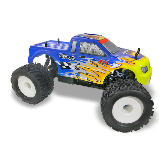
- Page 1 Strong Front and Rear chassis braces. Tuned Polished Dual Chamber racing pipe. INSTRUCTION MANUAL Unique adjustable chassis width of 310mm or 330mm. High performance .26 engine with Shaft Start Motor handle. Full race Offset King Pin aluminum steering knuckle. Three sealed differentials with 6 steel gears. Racing Stadium and Truck tire sets.
- Page 2 RTR KITS - REQUIRED FOR OPERATION You will need to buy a few items to start the engine and run the car. THINGS NEEDED • Use 20% nitro CAR fuel. Do not use airplane or heli fuels, they will over heat engine. •...
- Page 3 MUST READ THIS BEFORE RUNNING Running a nitro kit is fun and easy, but to make this a safe • Clean oil and dirt from chassis with a degreaser. and good experience you must observe a few rules. This Precautions kit is extremely fast, easily over 40MPH, and can seriously •...
- Page 4 Builds two differentials for front and rear. ASSEMBLE OF THE DIFFERENTIAL FOR FRONT AND REAR 40010 2.5x13.8mm Step 1 Step 2 40006 Cap Joint OPT : JS-01 94034 CNC Steel Diff. Gear Set 4x4mm 40010 Set Screw 2.5x13.8mm 40009 40004 O-Ring Diff.
- Page 5 ASSEMBLY OF THE FRONT GEAR BOX Insert two ball 40017 bearings as Gear Box shown. 36053 8X16mm Ball bearing Adjust the backlash 40024 with the shims. 13x16x0.2mm Shim 36053 8X16mm 40017 Ball bearing Gear Box 49012 Small Bevel Gear 94011 94011 ..X2 4x16mm...
- Page 6 ASSEMBLY OF THE FRONT SHOCK STAY 40116 Shock Tower 94010 4x12mm 94010 Hex Screw 4x12mm Hex Screw ..X2 94004 94010 3x12mm 94010 3x12mm 4x12mm Hex Screw Hex Screw ..X2 Hex Screw ASSEMBLY OF THE FRONT UPPER ARMS 40104 10mm Ball and Socket 40101 Front Upper 40101...
- Page 7 ASSEMBLY OF THE FRONT SUSPENSION ARMS Assembly of the right and left hand side are the same. Step 1 90021 E-Ring 90021 Step 2 E-Ring ASSEMBLY OF THE FRONT LOWER ARMS 40023 Lower Arm Shaft (4mm) Insert the rear drive shaft into cap joint before assembly the rear lower arm.
- Page 8 ASSEMBLY OF THE FRONT STABILIZER Assembly of the right and left hand side are the same. 40029 Step 1 Stabilizer Ball End ..X4 40290 3x10mm Hex Screw ..X2 30341 94005 Stabilizer Ball 3x16mm Hex Screw 94035 3x8mm ..X2 94035 Set Screw M3x8mm 40199 Set Screw...
- Page 9 ASSEMBLY OF THE REAR GEAR BOX 40017 Insert two ball bearings as Gear Box shown. 36053 8X16mm Ball bearing Adjust the backlash 40024 with the shims. 13x16x0.2mm Shim 36053 8X16mm 40017 Ball bearing Gear Box 49012 Small ..X2 Bevel Gear 94011 4x15mm 94011...
- Page 10 ASSEMBLY OF THE REAR SHOCK STAY Assembly of the right and left hand side are the same. 40116 Shock Tower 94010 4x12mm Hex Screw 94010 4x12mm ..X2 Hex Screw 94004 3x12mm Hex Screw 94004 3x12mm ..X2 Hex Screw ASSEMBLY OF THE UPPER ARM ROD Assembly of the right and left hand side are the same.
- Page 11 ASSEMBLY OF THE REAR SUSPENSION ARMS Assembly of the right and left hand side are the same. Step 1 90021 3.0mm E-Ring 90021 3.0mm E-Ring 40023 Lower Arm Shaft Step 2 90020 2.5mm E-Ring 90020 2.5mm E-Ring 40102 Plastic Washer 36170 3mm Arm Shaft 40102...
- Page 12 ASSEMBLY OF THE REAR STABILIZER Assembly of the right and left hand side are the same. Step 1 40029 Stabilizer Ball End 40290 3x10mm ..X4 Hex Screw 94005 30341 Stabilizer Ball 3x16mm ..X2 Hex Screw 94035 3x8mm Set Screw 94035 M3x8mm 40199 Set Screw...
- Page 13 ASSEMBLY OF THE SERVO SAVER Step 2 Step 1 94009 4x10mm 40037 40035 Hex Screw Steering Plat Servo Saver 40031 Hex Screw Alum. Tube 4x8mm 40031 Plastic flange Plastic Bushing Bushing 40037 40031 Steering Plat Servo Saver Hex Screw Horn A 40095 40030 Servo Saver...
- Page 14 ASSEMBLY OF THE BRAKE AND CENTER DIFF. MOUNT 36661 Remove the double-side Brake Pad tape before assembly. Linings G-06A Brake Pad Linings 36660 Brake Pad 40045 Step 1 Step 2 Brake Pad Adjustment Screw 40040 Center Diff. 40044 Mount 40044 Brake Pad Brake Pad Spring...
- Page 15 ASSEMBLY OF THE CENTER DIFF. INTO CENTER DIFF. MOUNT 94033 94003 3x3mm 3x10mm Step 1 Step 2 Step 3 Set Screw Hex Screw 30211 Plastic 40096 Bushing Center Diff. 30171 Plate Brake Lever 30211 30213 Plastic Brake Cam Bushing 30213 Brake Cam 94003 3x10mm...
- Page 16 ASSEMBLY OF THE CENTER STIFFENER ONTO CHASSIS 90018 3x25mm Cap Screw 35313 40018 Nylon Nut Center Chassis 40018 Brace Center Chassis ( Front ) Brace ( Rear ) 94004 3x12mm Hex Screw 35313 M3 Nylon Nut ..X1 94004 3x12mm Hex Screw ..X1 94027 4x16mm...
- Page 17 ASSEMBLY OF THE RADIO TRAY Step 1 94003 Step 2 49039 3x10mm Alum. Hex Screw Radio Tray 94003 3x10mm 94003 94003 Hex Screw 3x10mm 3x10mm Hex Screw Hex Screw 40027 Radio Tray 94003 94003 Post 3x10mm 3x10mm ( Plastic ) Hex Screw Hex Screw Throttle...
- Page 18 ASSEMBLY OF THE RADIO TRAY ONTO CHASSIS 94019 3x10mm Flat Head Hex Screw 94019 94019 94019 3x10mm 3x10mm 3x10mm Flat Head Hex Flat Head Hex Flat Head Hex Screw Screw ..X2 Screw ASSEMBLY OF THE SHOCKS * Builds 4 for Shocks. Step 1 Step 2 32237...
- Page 19 ASSEMBLY THE DUST COVER AND SHOCK SPRING 40089 Step 1 Step 2 Shock Spring (Black) 30411 Ball 40058 Shock Shaft Dust Cover Push 6mm ball joint into ball end. 40063 Spring Holder ASSEMBLY OF THE FRONT SHOCK ABSORBERS Assembly of the right and left hand side are the same. 90018 3X25mm Screw...
- Page 20 ASSEMBLY OF THE BODY POST 94004 3x12mm 94010 4x12mm Hex Screw 40117 Hex Screw Body Support Plastic 2.6x15mm Screw 40117 Body Post Plastic 94042 Nylon Nut 2.6x15mm Screw 40117 Body 94010 4x12mm Hex Screw 35313 Nylon Nut 40117 Body 94012 4x20mm Hex Screw (FRONT)
- Page 21 ASSEMBLY OF THE FUEL TANK Step 1 Step 2 Pressure Nipple 94005 3x15mm Hex Screw 94005 3x15mm Hex Screw Pressure Nipple 40109 Fuel Tank 40047 Fuel Tank 40047 Post * Take the fuel tank Fuel Tank post from J-42 Post plastic parts tree.
- Page 22 ASSEMBLY OF THE CLUTCH INTO ENGINE 3 x 5mm Screw Notes: Non-Pull Start Engines... • Alum. Washer behind the flywheel is not needed when using Force engines or similar types. O.S. Engines will require washer spacer. 10099 3 X 8mm •...
- Page 23 ASSEMBLY OF THE MANIFOLD AND MUFFLER Step 1 Step 2 10068 Manifold Adapter 10120 Manifold Spring 10060 Manifold Nylon Straps (Middle) Option: 10182 Silicone Tube, Red 10184 Silcone Tube 10183 Silicone Tube, Yel. 31992 10184 Pipe Silicone Tube, Blue ASSEMBLY OF THE ENGINE ONTO CHASSIS Spur Gear Clutch Bell 90 degree...
- Page 24 ASSEMBLY OF THE FUEL TUBE Step 1 Step 2 Connect to fuel nipple. 10179 Fuel Tube Connect to fuel tank pressure nipple. Connect to carbulater. 10179 Fuel Tube Connect to pressure nipple. ASSEMBLY OF THE BUMPER 40204 Front Bumper 94004 3x12mm Screw 94004...
- Page 25 ASSEMBLY OF THE FRONT STEERING ROD 94004 Step 1 Step 2 3X12mm Hex Screw 10768 Servo Horn 30410 Use the screw provided with Ball 94004 your servo. 3X12mm #312 Hex Screw Servo Horn Adapter 30410 30410 Plastic Ball Plastic Ball 30690 3x30mm Tie Rod...
- Page 26 ASSEMBLY OF THE BRAKE LINKAGE INTO BRAKE LEAVE 3x3mm Set Screw USING BREAK ADJUST NUT #158 Alum Tighten or loose the adjuster nut will Stopper change the brake. 3x3mm Set Screw Loose Tighten More Brake Less Brake use the screw provided With your radio.
- Page 27 ASSEMBLY OF THE TIRES AND WHEELS Step 1 Step 2 86070 Stadium Tires Apply instant glue into the groove of the wheel. B-21 Inner Sponge 86069 Stadium Wheel ASSEMBLY OF THE TIRE ONTO FRONT KNUCKLE AND REAR HUB Assembly of the right and left hand side are the same. Tire and Wheel assembly.
- Page 28 ASSEMBLY OF THE TIRES AND WHEELS Step 1 Step 2 Right - side Left - side Notice the direction of the tyres. 86101 Notice the direction of the tyres. Truck Wheel B-25 Truck Inner Sponge 86100 Truck Tire. LZ Thread 86100 Truck Tire.
-
Page 29: Setting Guide
SETTING GUIDE FRONT CAMBER ANGLE SETTING REAR CAMBER ANGLE SETTING Negative Positive Positive Negative Turnbuckle Turnbuckle Place the model car on flat surface. Raise the chassis to it's maximum clearance before the wheels leave the ground. Adjust the length of the front and rear upper arms so that the wheels are right angle to the ground. The camber angle adjustment can be moving the turnbuckle rod on the upper arms, clockwise or anti-clockwise. - Page 31 APPENDIX PAGES...
- Page 32 SHAFT START NOTICE: 9.5 BLAZER RTR KITS WILL COME WITH “SHAFT START #50000” (same as Rotor Start). THEREFORE, A PULL START ENGINE IS NOT USED AND THE SHAFT START FORCE BACK PLATE (#50010) IS ALREADY INSTALLED. BEFORE YOU CAN USE THE SHAFT START MOTOR HANDLE, YOU MUST FIRST GET OR BUY A STANDARD 7.2 BATTERY PACK.
- Page 33 TUNING AFTER BREAK-IN Close master needle by turning clockwise until it stops. Then open needle by turning counterclockwise 3 turns When running car, adjust carb with 1/8 clockwise turns, (rich setting). slowly leaner, until the top speed good. Check engine temp, if possible, for no more 250 degrees.
- Page 34 OFNA MICRO FAIL SAFE UNIT - #91002 (MICRO) The OFNA Fail Safe unit is used to protect your RC car from loss of control due to: • Weak radio signal • Low radio batteries • Radio interference of any kind •...
- Page 35 BLAZER SST RTR ( 9.5 VIOLATOR) KIT 10010 SHOES, 3 SHOE TYPE, BLACK, 3 PCS. 12.95 10011 SHOES, 3 SHOE TYPE, WHITE, 3 PCS. 13.95 10017 AIR FILTER, FOAM, BLUE 5.95 10021 1:8 BLK, SILICONE FILTER TUBE, 90 DEG. L SHAPE 4.95...
- Page 36 40025 REAR, LOWER ARM ALUM. HOLDER 11.95 40028 CENTER SHAFTS, DOG BONES 93MM PAIR 19.95 40029 BALL ENDS, PLASTIC, ANTI-ROLL BAR 3.95 40030 FRONT PLATE, ALUM. BLUE 8.95 40031 SERVO SAVER HORN 15.95 40032 PLATE, SERVO SAVER ALUM. SLIDER BLUE 10.95 40033 SPRING, SERVO SAVER...
-
Page 38: Owner's Registration Card
The registration card should be filled out and mailed to OFNA Racing within 10 days of purchase date. In the event that the kit is incomplete or component parts are broken due to error in manufacturer, contact your dealer from which you purchased the kit for replacement part or call OFNA at (949) 586-2910 for your nearest dealer location.
Need help?
Do you have a question about the BLAZER SST and is the answer not in the manual?
Questions and answers