Table of Contents
Advertisement
Betriebsanleitung
Operating manual .................p. 24
Mode d'emploi .......................p. 48
Istruzioni per l'uso .................p. 71
Airless Hochdruck-Spritzgerät
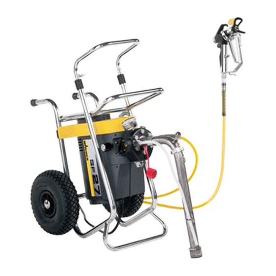
Airless high-pressure spraying unit
Groupe de projection à haute pression
Impianto per la verniciatura a spruzzo ad alta pressione
Ausgabe
03/2009
Edition
Edizione
Super Finish 27 • 31
Airless
0341 855
Advertisement
Table of Contents

Related Manuals for WAGNER Super Finish 27


Summary of Contents for WAGNER Super Finish 27
- Page 1 Mode d’emploi .......p. 48 Istruzioni per l’uso ....p. 71 Airless Hochdruck-Spritzgerät Airless high-pressure spraying unit Groupe de projection à haute pression Airless Impianto per la verniciatura a spruzzo ad alta pressione Super Finish 27 • 31 Ausgabe 03/2009 0341 855 Edition Edizione...
- Page 2 The operating instructions state that the following points must always be observed before starting up: 1. Faulty units must not be used. 2. Secure WAGNER spray gun using the safety catch on the trigger. 3. Ensure that the unit is properly earthed. The connection must take place through a correctly earthed two-pole and earth socket outlet.
-
Page 3: Table Of Contents
2.1 Application _________________________________ 27 Accessories illustration for Super Finish 27 and 31 __ 95 2.2 Coating materials ____________________________ 27 12.2 Spare parts list pump head Super Finish 27 and 31 _ 43 deScrIptIon oF unIt ___________________ 28-30 Spare parts diagram pump head 3.1 Airless process _______________________________ 28... -
Page 4: Safety Regulations For Airless Spraying
Always secure the spray gun when mounting or dis- mounting the tip and in case of interruption to work. do not load the socket with more than 1000 watt. unroll any connected cable drum completely. Super Finish 27 • 31... -
Page 5: General View Of Application
In spite of the suction filter, the insertion filter in the spray gun and the high-pressure filter obtainable as accessory, filtering of the coating material is to be recommended in general. Stir coating material before commencement of work. Super Finish 27 • 31... -
Page 6: Description Of Unit
In the following there is a short description of the technical construction for better understanding of the function. WAGNER Super Finish 27 and 31 are electrically driven high- pressure spraying units. The electric motor (fig. 2, item 1) drives the pump by means of a toothed belt (2). -
Page 7: Explanatory Diagram
Extractable shaft Tool box* Eyelet stop for the spray gun * with Super Finish 31 Horizontal set-up with upper hopper Upper hopper, capacity 5 litres Return pipe (not positioned parts as in g. 3) Super Finish 27 • 31... -
Page 8: Horizontal Set-Up With Upper Hopper
Extract shaft to the desired length. Tighten terminal sleeves again by hand ( closed). unIt wIth upper hopper (5 lItreS) Screw off dust protection cap (fig. 7, item 1). Pay attention to clean sealing areas on the connections. Super Finish 27 • 31... -
Page 9: High-Pressure Hose And Spray Gun
Leave the unit on for two to three minutes. right until Then turn the pressure regulating knob (1) to the stop. Sound of the inlet valve is audible. If not, repeat points 1 and 3. Super Finish 27 • 31... -
Page 10: Starting Operation Of Unit With Coating Material
Completely unroll a connected cabledrum. Attention So that in switching on the unit the mains fuse protection of 16 A does not react: Always switch on the Super Finish 27 or31 unit first and then the connected unit. Attention SprayIng technIque Guide the spray gun evenly during the spraying process. -
Page 11: Cleaning Unit (Shutting Down Operation)
Close spray gun. When cleaning with water, repeat procedure for about three First of all pull out mains plug from socket. minutes with clear water. Danger Switch off unit – set multifunction switch to (OFF). Super Finish 27 • 31... -
Page 12: Suction Filter
Open high-pressure filter and clean filter insert; in addition: Insert open-ended spanner into the groove of the filter housing (fig. 15, item 1) – screw out filter housing. Remove filter housing (1), supporting part (2), centring ring Super Finish 27 • 31... -
Page 13: Remedy In Case Of Disturbance
Check voltage supply • • Fuse protection has reacted. For example First switch on the unit Super finish 27 or an agitator is connected to the socket 31 and then, for example, the connected on the unit. This agitator has not been agitator. -
Page 14: Servicing
Check oil level (fig. 18) in the horizontal set-up. 10.2 hIgh-preSSure hoSe Check high-pressure hose optically for any cuts or bulges in particular at the connection to the fitting. Union nuts must be able to be turned freely. Super Finish 27 • 31... -
Page 15: Repairs On The Unit
(2) presses parts out 3 to 4. Attention Clean or replace individual parts. Check O-ring (6) for damage. Pay attention to installation position in mounting spring support ring (3), outlet valve seat (4) and seal ring (5), see fig. 21. Super Finish 27 • 31... -
Page 16: Pressure Regulating Valve
Turn regulating knob into switch position (spray). Only in item 1) into switch position (spray). this position can the stop screw (fig. 23, item 2) be pushed Remove regulating knob. in by hand and screwed tight. Super Finish 27 • 31... -
Page 17: Exchanging Diaphragm
Before mounting, clean and dry diaphragm, insert and built-in areas on screw flange (6) and on paint section (3). Mounting takes place in the reverse order First of all tighten hexagonal screws (1) with 10 Nm, then crosswise with 70 Nm. Super Finish 27 • 31... -
Page 18: Circuit Diagram
Repairs on the unit 11.8 Schaltplan Super Finish 27 • 31... -
Page 19: Accessories And Spare Parts
Accessories and spare parts acceSSorIeS and Spare partS 12.1 acceSSorIeS For Super FInISh 27 and 31 Item SuperFinish 27 SuperFinish 31 Description Order no. Order no. accessories illustration, see page 42 0341 705 --------------------- Inlet valve – trigger housing 0341 713... -
Page 20: Accessories Illustration For Super Finish 27 And 31
Accessories and spare parts accessories illustration for Super Finish 27 and 31 Super Finish 27 • 31... -
Page 21: Spare Parts List Pump Head Super Finish 27 And 31
Item SuperFinish 27 SuperFinish 31 Description 12.2 Spare partS lISt pump head Order no. Order no. Super FInISh 27 and 31 0341 350 0341 350 Double socket (SPARE PARTS DIAGRAM, SEE PAGE 96) M 16 x 1.5 0344 337 -------------------... -
Page 22: Spare Parts List Pump Aggregate Super Finish 27 And 31
0341 446 Suction hose 0341 307 0341 307 Seal *When exchanging these parts the operating pressure must 0341 309 0341 309 Cover be reset by the customer service. 3050 858 3050 858 Disk 5,3 (6) Super Finish 27 • 31... -
Page 23: Appendix
Order no. 0999 321 Length 100 cm Length 30 cm Order no. 0096 016 Order no. 0999 322 Length 200 cm Length 45 cm Order no. 0096 017 Order no. 0999 323 Length 300 cm Length 60 cm Super Finish 27 • 31... -
Page 24: Airless Tip Table
0552 243 50° 0.043 / 1.10 0552 543 50° 0.052 / 1.30 0552 552 1)Spray width at about 30 cm to the object and 100 bar (10 MPa) pressure with synthetic-resin paint 20 DIN seconds. Super Finish 27 • 31... - Page 25 Accessories illustration Illustration des accessoires Figura degli accessori Super Finish 27 • 31 Super Finish 27 • 31...
- Page 26 Spare parts diagram Illustration des pièces de rechange Schema pezzi di ricambio Super Finish 27 • 31 pumpenkopf pump head (SF31) (SF27) tête de pompe testa della pompa (SF27) Super Finish 27 • 31...
- Page 27 Sistema di aspirazione oberbehälter 5 liter oberbehälter 20 liter upper hopper, 5 litres upper hopper, 20 litres cuve de gravité 5 litres cuve de gravité 20 litres contenitore superiore da 5 litri contenitore superiore da 20 litri Super Finish 27 • 31...
- Page 28 Spare parts diagram Illustration des pièces de rechange Schema pezzi di ricambio Super Finish 27 • 31 pumpen-aggregat pump aggregate Groupe de pompe Aggregato pompe Super Finish 27 • 31...
-
Page 29: Declaration Of Conformity
Once the guarantee period has expired, claims made against the guarantee or from the guarantee can no longer be en- forced. Wagner or one of our dealers will take back your used Wagner waste electrical or electronic equipment and will dispose of 3. handling it for you in an environmentally friendly way. - Page 30 Claims for liability for defects to the specialist trader remain unaffected. German law applies to this guarantee. The contractual lan- guage is German. In the event that the meaning of the German and a foreign text of this guarantee deviate from one another, Super Finish 27 • 31...
Need help?
Do you have a question about the Super Finish 27 and is the answer not in the manual?
Questions and answers