
Related Manuals for BONAIRE B007RS


Summary of Contents for BONAIRE B007RS
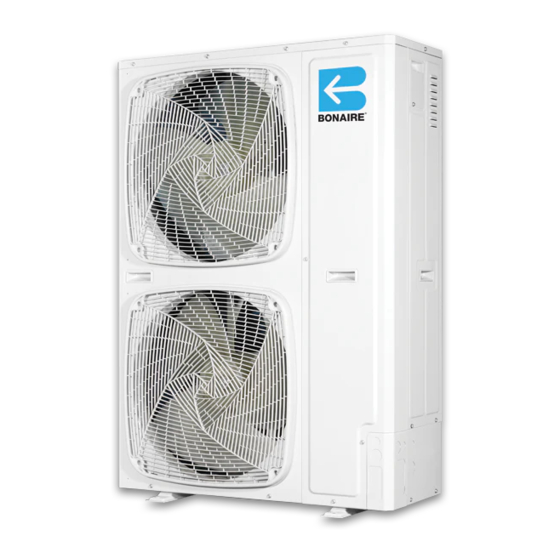
- Page 1 Installation Manual UCTED EVERSE YCLE EFRIGERATED ONDITIONING B007RS, B009RS, B012RS, B015RS, B016RT, B019RT...
-
Page 3: Table Of Contents
UCTED EVERSE YCLE EFRIGERATED ONDITIONING Table of Contents General ............................4 UNIT DETAILS ..........................5 Outdoor Unit Dimensions ......................5 Outdoor Unit Access and Clearances ................... 7 Indoor Unit Dimensions ......................... 8 Indoor Unit Clearances ......................... 9 UNIT INSTALLATION ........................10 Indoor Installation........................ -
Page 4: General
General ENERAL Bonaire Ducted Reverse Cycle air conditioners include two separate units – Indoor and Outdoor Unit. The two units are interconnected by two refrigerant tubes and an electric cable. Unit functions are controlled by a Radio Frequency Remote controller or a hard wired low voltage controller (depending on the option purchased). -
Page 5: Unit Details
UCTED EVERSE YCLE EFRIGERATED ONDITIONING Dimensions & Clearances Unit Details UTDOOR IMENSIONS B007RS B009RS B012RS Unit Weight B007RS 60kg Connections Inside Unit B009RS 92kg B012RS 97kg Page 5... - Page 6 UCTED EVERSE YCLE EFRIGERATED ONDITIONING Dimensions & Clearances B015RS B016RT B019RT Unit Weight B015RS 103kg 1260 Connections Inside Unit B016RT 108kg 1260 Connections Inside Unit B019RT 131kg 1460 Page 6...
-
Page 7: Outdoor Unit Access And Clearances
UCTED EVERSE YCLE EFRIGERATED ONDITIONING Dimensions & Clearances UTDOOR CCESS AND LEARANCES When the back is close to the Wall In selecting a proper location, the following criteria The top and the front need to be open. This includes protruding window sills. must be considered: The outdoor unit and the indoor unit must be installed as close to each other as possible, within... -
Page 8: Indoor Unit Dimensions
UCTED EVERSE YCLE EFRIGERATED ONDITIONING Dimensions & Clearances NDOOR IMENSIONS Unit Dimensions Unit Weight B007HD 39Kg B009HD 39Kg B012HD 46Kg 1181 1126 1066 B015HD 46Kg 1181 1126 1066 B016HD 49Kg 1301 1246 1071 1186 B019HD 53Kg 1301 1246 1071 1186 Page 8... -
Page 9: Indoor Unit Clearances
UCTED EVERSE YCLE EFRIGERATED ONDITIONING Dimensions & Clearances NDOOR LEARANCES Clearance Options for Maintenance (Mandatory) Fan Removal Clearances Options Unit A + B B007HD B009HD B012HD B015HD B016HD B019HD Page 9... -
Page 10: Unit Installation
UCTED EVERSE YCLE EFRIGERATED ONDITIONING Unit Installation Unit installation NDOOR NSTALLATION Page 10... -
Page 11: Indoor Unit Location
UCTED EVERSE YCLE EFRIGERATED ONDITIONING Unit Installation Indoor Unit Location The indoor unit is designed for installation within a ceiling/roof space or other compartment, where there is no influence from outdoor conditions. While selecting the location, the following conditions must be assured: a) The location should assure free flow of the return air into the unit without interference. -
Page 12: Floor Or Platform Mounting
UCTED EVERSE YCLE EFRIGERATED ONDITIONING Unit Installation Floor or Platform Mounting 1. Create a platform using bearers and chipboard. Place the unit platform over load bearing walls or on strategically located trusses in the roof space. 2. Place serrated rubber pads or isolating springs under each corner of the unit to minimize / eliminate any noise transmission. -
Page 13: Outdoor Unit
UCTED EVERSE YCLE EFRIGERATED ONDITIONING Unit Installation UTDOOR Page 13... -
Page 14: Condenser Installation
UCTED EVERSE YCLE EFRIGERATED ONDITIONING Unit Installation ONDENSER NSTALLATION Installation on flat surface (roof, ground, etc) Install outdoor unit support in a position elevated at least 100 mm on a concrete pad, concrete block or wooden beams, in order to allow free water flow underneath. -
Page 15: Installation Notes
TUBING LENGTH, UP TO – (IN METRES, ONE WAY) MAXIMUM MAXIMUM MODEL LINE TUBING HEIGHT LENGTH DIFFERENCE 15.88mm (⅝”) 15.88mm (⅝”) 19.05MM (¾”) B007RS Liquid 9.58mm (⅜”) 9.58mm (⅜”) 9.58mm (⅜”) 19.05MM (¾”) 19.05MM (¾”) 19.05MM (¾”) 22.23mm (⅞”) B009RS Liquid 9.58mm (⅜”) 9.58mm (⅜”)”... -
Page 16: Recommendation For Interconnection Tubing Installation
UCTED EVERSE YCLE EFRIGERATED ONDITIONING Unit Installation Recommendation for Interconnection Tubing Installation Three possible versions are schematically illustrated: 1) The outdoor unit installed above the indoor unit – such installation requires an oil trap in the gas line at the lowest point of the riser. The radius of the oil trap should be as short as possible. -
Page 17: Pipe Installation
UCTED EVERSE YCLE EFRIGERATED ONDITIONING Unit Installation NSTALLATION WARNING This paragraph describes the necessary steps for setting the unit into operation. Be sure to follow the instructions, to assure proper functioning of the air conditioner. The outdoor unit is pre-charged with the correct amount of refrigerant. In extended runs, for additional refrigerant charge please refer to the outdoor unit name plate. -
Page 18: Pipe Welding
UCTED EVERSE YCLE EFRIGERATED ONDITIONING Unit Installation Pipe Welding Take care when using brazing flame torch, ensure that hot pipes or flame do not cause a fire 1. Use quality brazing rod suitable for copper to copper joins on refrigeration grade tubing. 2. -
Page 19: Evacuation And Setting In Operation
UCTED EVERSE YCLE EFRIGERATED ONDITIONING Unit Installation VACUATION AND SETTING IN OPERATION a) Connect two charging hoses from the charging set to the outdoor unit as shown in the diagram below. b) Connect the centre hose of the charging set to a vacuum pump. c) CAUTION - turn on the vacuum pump and make sure that the low pressure gauge reading moves from 0 kPa to -100 kPa;... -
Page 20: Additional Charge
UCTED EVERSE YCLE EFRIGERATED ONDITIONING Unit Installation DDITIONAL HARGE 1. Add 57 grams per meter of 9.53 (3/8”) liquid line over and above the specified system pre- charged length. See the unit name plate for this information. DO NOT exceed the maximum equivalent pipe length on each unit. -
Page 21: Electrical Connections
UCTED EVERSE YCLE EFRIGERATED ONDITIONING Electrical Electrical Connections WARNING 1. Electrical connection shall be made only by authorized electricians and in accordance with local electrical requirements and codes. 2. The system must be grounded. 3. Single phase models and three phase models are available; for each of them, the necessary wiring diagram is shown. -
Page 22: Outdoor Unit Connections
PCB. Use supply wire sizes as per local electrical codes and regulations. Recommended Full Load Recommended Model Circuit Breaker Amps Cable Size B007RS 14.5 2.5mm B009RS 16.5 4.0mm B012RS 21.8 4.0mm B015RS 32.4... -
Page 23: Wiring Diagram - Single Phase Outdoor Unit
UCTED EVERSE YCLE EFRIGERATED ONDITIONING Electrical IRING IAGRAM INGLE HASE UTDOOR Page 23... -
Page 24: Wiring Diagram - 3 Phase Outdoor Unit
UCTED EVERSE YCLE EFRIGERATED ONDITIONING Electrical - 3 P IRING IAGRAM HASE UTDOOR Page 24... -
Page 25: Control Installation
UCTED EVERSE YCLE EFRIGERATED ONDITIONING Control Installation Control Installation EFORE TARTING Before attempting to use the setup instructions for the controls system, make sure the antenna (RF units only) or the low voltage cable is connected, batteries have been correctly installed in the remote control (RF units only) and the 240 or 415 volt power has been turned on to the product. -
Page 26: Setting Up The Thermostat
UCTED EVERSE YCLE EFRIGERATED ONDITIONING Control Installation Setting Up the Thermostat Radio Frequency 1) Place the 3 AAA batteries supplied into the thermostat. Make sure they are correctly rotated to ensure the thermostat screen initialises. Battery replacement requirements will be indicated via the thermostat screen. -
Page 27: Commission
UCTED EVERSE YCLE EFRIGERATED ONDITIONING Commissioning Commission PERATING ARAMETERS Led Operation FUNCTION RED LED1 FLASH HUSH GREEN LED2 (STATUS) QUICK HIGH ETTING THE PERATING ARAMETERS 1. To enter the setup mode press and hold both the ‘FUNCT’ and ‘SELECT’ buttons for a period of 5 seconds then release both buttons, a successful operation will be indicated by both 'Red Led1' and 'Green Led2' turning on for 2 seconds. -
Page 28: Led Operation And Interpretation
UCTED EVERSE YCLE EFRIGERATED ONDITIONING Commissioning Function: Installer commissioning mode (setup/service) Action: Hold ‘FUNCT’ button for 10 seconds then release to initiate commissioning mode sequence. This will be indicated by two flashes of the ‘Red Led1’. Result: Immediately after this has been selected the system will operate in the following mode; All safety and fault sensing functions will be disabled for a period of 45 minutes or if power is interrupted or if the controller has been reset by the reset function, which ever occurs first. -
Page 29: Commissioning Check List
UCTED EVERSE YCLE EFRIGERATED ONDITIONING Commissioning OMMISSIONING HECK Site □ Return panels and covers to their correct position and check that they are well secured. □ Ensure all service caps are fitted and correctly tightened. □ Attach the electrical wires and pipes to the wall with clamps. □... - Page 30 UCTED EVERSE YCLE EFRIGERATED ONDITIONING Commissioning Customer Handover Explain to the customer together with the operating instructions: □ How to remove, clean and replace the filter □ How to turn the air-conditioner on and off. □ How to choose between heating and cooling and how to set the desired temperature. □...
- Page 32 Manufactured by Climate Technologies ABN 13 001 418 042 26 Nylex Avenue Salisbury, SA 5108 Australia www.climatetechnologies.com.au 6602204/D...
Need help?
Do you have a question about the B007RS and is the answer not in the manual?
Questions and answers