YouKits TJ5A Operation Manual
Ssb cw hf transceiver
Hide thumbs
Also See for TJ5A:
- Operation manual (11 pages) ,
- Operation manual (13 pages) ,
- Manual to alignment (3 pages)
Advertisement
Quick Links
Download this manual
See also:
Operating Manual
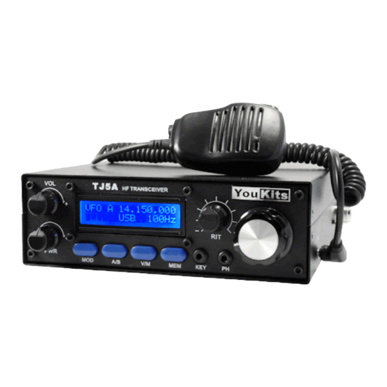
Youkits TJ5A SSB CW HF TRANSCEIVER
TJ5A is a high-performance portable multi-band SSB/CW transceiver, used with DDS as
LO, offering wide frequency coverage and fine tuning rate. The Doubly Balanced Diode
Ring Mixer makes strong signal handling capability possible.
Features:
Removable Battery Pack
Low RX current Drain
High-Performance AGC
40 Memories
Dual VFO
Memory-VFO Transfer
Operating Frequency:
Wide Band RX
3.500000 - 29.699990
TX / Narrow Band RX
7.000000 – 7.300000
14.000000 – 14.350000
21.000000 – 21.450000
28.000000 – 29.700000
Mode:
LSB, USB, CW
Tuning Rate: 10Hz, 100Hz,
1kHz, 10kHz, 100kHz
IF: 9 MHz
Sensitivity: 0.3uV Operating Power: 10.5 – 12.5V
Current Drain:
MODE
RX
TX
Output Power:
MODE
SSB
CW
OPERATION GUIDE
CURRENT
0.26 A
4 A
OUTPUT
0.1 – 20W
0.1 – 10W
1
Advertisement

Related Manuals for YouKits TJ5A


Summary of Contents for YouKits TJ5A
- Page 1 Youkits TJ5A SSB CW HF TRANSCEIVER OPERATION GUIDE TJ5A is a high-performance portable multi-band SSB/CW transceiver, used with DDS as LO, offering wide frequency coverage and fine tuning rate. The Doubly Balanced Diode Ring Mixer makes strong signal handling capability possible.
- Page 2 1. Face Panel Knobs VOL - Volume control. Turn clockwise to increase volume. TUNE – The big knob on the right side is Frequency tuning knob/Tuning rate selector. Rotate clockwise is frequency up, counter-clockwise frequency down. Press the knob to select the tuning rate.
- Page 3 MEM - Frequency saving / MEM to VFO transfer. Press to save the frequency to the memory. Press MEM, the memory number appears. The dashes indicate the blank state of the memory. Turn TUNE to select the MEM position you want to store the frequency to. MEM00 - MEM39 can be used to store the frequency.
- Page 4 Select VFO B by pressing A/B button or rotating TUNE knob. Press MEM to transfer MEM 00. The following is displayed: Press V/M to enter VFO B. Sockets KEY – CW key socket. Use 3.5mm stereo plug. The ring is KEY; the sleeve is GND. The tip has no connection.
- Page 5 PH - Earphone/speaker 3.5 mm socket. Either earphones or speaker can be used. When the earphone or speaker is plugged in, the speaker in MIC is disconnected. The tip and ring are in parallel. The sleeve is GND. The stereo earphones can be used. Never use the 3.5mm mono type plug.
- Page 6 2. Switch and Socket on Right Side MIC - External MIC/PTT/SPK socket. The supplied handset is also used as the speaker. When the front PH socket is used, the MIC speaker is disconnected. ON - When the switch is set at this position, the power is switched on, and the rig works. OFF - When the switch is set at this position, the power is off.
- Page 7 IMPORTANT! The power supply socket on the back (DC IN) has three pins: the “+” pin (left) and “-”pin (right). The pin in the middle is also “-” pin which is for battery operation. For DC12.5V external power supply operation, use the 3-pin connector. The left pin is “+”, and the right pin is “-”.
- Page 8 The two supplied white plastic bushes are used to prevent the paint from scratching by the battery cabin screws. Put them on the screws before fastening the cabin to the transceiver back.
- Page 9 If you do not have the battery pack, use a DC 12.5 V power supply (The battery pack is optional. Not included in the rig). Warming-up time It takes about 10 minutes for the TJ5A to stabilize. A drift of 10 – 20 Hz might be noticed during the warming-up period. To receive signal Connect the antenna and turn on the power.
- Page 10 The LED at the right corner of the main board indicates the IF working state. It flashes at very strong signals because of the AGC function. To transmit signal TJ5A transmits in the following frequency range: Meter Band Frequency Range 7.000000 –...
- Page 11 Open the upper cover the TJ5A. Find VR3. Set the power level to the lowest. Press KEY and trim VR3 until the desired side tone level is obtained. IMPORTANT! Never try the long key at the full power output. This would overheat the power transistors.
Need help?
Do you have a question about the TJ5A and is the answer not in the manual?
Questions and answers