Table of Contents
Advertisement
Quick Links
Download this manual
See also:
Owner's Manual
Advertisement
Table of Contents

Subscribe to Our Youtube Channel
Related Manuals for Audison LRX6SR


Summary of Contents for Audison LRX6SR
- Page 1 CAR POWER AMPLIFIER...
- Page 2 INTRODUCTION INTRODUCTION Audison thanks you for preferring this product and compliments you on your choice since it was designed in order to insure outstanding musical and instrumental performances. Before use instructions, please carefully read the safety norms you have to respect in order to avoid unpleasant inconveniences and to enjoy this product at best.
-
Page 3: Table Of Contents
........ -
Page 4: Description
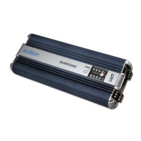
DESCRIPTION Audison LRx 6.SR Direct: Six channel car power amplifier characterised by excellent musical performances, small size and outstanding energy reserve. Its PWM power supply stage is made with two pairs of 70A MOSFETs; it is stabilised and oversize. Input stage is provided with a special circuit (LNS) which allows the system disturbances rejection, reducing noise that is usually due to the vehicle electric parts (alternator, electronic injection, etc.),... -
Page 5: In-Out Panel
IN-OUT PANEL FUNCTIONS... -
Page 6: Power Supply Panel
POWER SUPPLY PANEL FUNCTIONS... -
Page 7: Fuse Replacement
POWER SUPPLY PANEL FUSE REPLACEMENT 1 - Open the transparent cover by pushing the two teeth in its lowest corners to the direction indicated by the arrows. 2 - Remove the screws which fasten the fuse to eliminate pieces of the broken one; prevent them from going into the device. -
Page 8: Controls Panel
CONTROLS PANEL FUNCTIONS AND CONTROLS... - Page 9 CONTROLS PANEL...
-
Page 10: Setting Panel
SETTING PANEL FUNCTIONS It permits to reach the resistors to set subsonic filter cut-off frequency, the switch which activates subsonic filter (SUBSONIC) and to insert VCA modules for the subwoofer volume remote control. Setting panel 1 - Remove the setting panel in the amplifier bottom in order to carry out operations. -
Page 11: Subsonic Filter Cut-Off Frequency Modification
SETTING PANEL SUBSONIC FILTER CUT-OFF FREQUENCY MODIFICATION Subsonic filter is pre-adjusted at 20 Hz. In order to modify this value, please act according to what follows. Procedure: Replace FS1, FS2, FS3, FS4 resistors according to the values in the setting panel table. Remark: Cut the new resistors rheophores according to the size in the picture. -
Page 12: Technical Features
TECHNICAL FEATURES SIZE FOR FIXING 445 mm 412 mm Drilling dimensions for fixing LRx 6.SR Direct POWER SUPPLY Output power (RMS) @ 13.8 VDC; THD 1% Voltage: ......11 ÷ 15 VDC - A config.: 55W x 5 (4 Ohms) + 150W x 1 (4 Ohms) Idling current: . -
Page 13: Accessories
ACCESSORIES VCRAK and VCRDK LRx 6.SR Direct can accept one of the optional kits that allow the subwoofer volume remote control. VCRAK is analogic and special for sub; VCRDK is digital and can be used for master volume control or for level control of any ways in a multichannel system. -
Page 14: Clk2 - Lrx Cooling Kit
ACCESSORIES CLK2 – LRx Cooling Kit This cooling system is specially designed to provide LRx amplifiers with the right working temperature. CLK2 should be used when LRx amplifiers work in extremely hard conditions (very low loads) or in installations where space is too narrow and heat sink cooling is not enough. It consists of two units to apply onto the amplifier sides;... -
Page 15: Configurations
CONFIGURATIONS BLOCK DIAGRAM... -
Page 16: Controls Panel Diagram And Subsonic Filter Switch
CONFIGURATIONS CONTROLS PANEL DIAGRAM AND SUBSONIC FILTER SWITCH CONFIGURATION EXAMPLE FRONT+REAR+CENTER+SUB... -
Page 17: Installation
3 - Remove the strip with audison logo. 4 - Put the strip back again after turning it, so that audison logo is upside down. 5 - Mount the plate back by fixing it through the screws;... -
Page 18: Amplifier Fixing
INSTALLATION AMPLIFIER FIXING COLLEGAMENTI ELETTRICI CAUTION For the system safer protection, we recommend the use of a strip fuse on the cable that connects the battery positive pole to the amplifier POWER (+) terminal block.This fuse has to be installed about 10 cm far from the battery;... -
Page 19: Audison Cable Products For Electric Connections
INSTALLATION audison cable PRODUCTS FOR ELECTRIC CONNECTIONS... -
Page 20: Audison Measurement Standards
- The nominal power of the amplifier is measured upon a battery voltage of 12 Volts with a 4 Ohm load and with all channels in function. 62018 Potenza Picena (MC) Italy • Tel. 0733.870870 • Fax 0733.870880 • http://www.audison.com...
Need help?
Do you have a question about the LRX6SR and is the answer not in the manual?
Questions and answers