Table of Contents
Advertisement
AUTOMATIC SILENT COMPRESSORS
automatische leiselaufkompressoren
15 A
30/4
30 HA
30/6
30/12
50/9
50/12
100/24
100/50
Manufacturer - Hersteller
WERTHER INTERNATIONAL S.p.A.
via F. Brunelleschi, 12
42124 Cadè (RE) - Italy
Telefono/Phone ++/+522/9431
Fax
++/+522/941997
E-MAIL sales@wertherint.com
WEB http://www.wertherint.com
15 D
15 TC
30 D
50 D
50/15
150/50
15 TDC
30 TC
50 TC
50/24
200/100
Authorized service center
Zugelassenes Kundendienstzentrum
Rev.5................... 01/02/2012
15 EXPORT A
30 TDC
50 TDC
50 TDC
Advertisement
Table of Contents

Related Manuals for WERTHER INTERNATIONAL 15 A


Summary of Contents for WERTHER INTERNATIONAL 15 A
- Page 1 AUTOMATIC SILENT COMPRESSORS automatische leiselaufkompressoren 15 A 15 D 15 TC 15 TDC 15 EXPORT A 30/4 30 HA 30 D 30 TC 30 TDC 30/6 30/12 50 D 50 TC 50 TDC 50/9 50/12 50/15 50/24 50 TDC 100/24...
-
Page 2: Important Note
Contents Inhaltsverzeichnis 1 General information 1 Allgemeines 1.1 Importance and use of the manual..3 1.1 Hinweise zu dieser Anleitung ....3 1.2 Content ...........3 1.2 Inhalt..........3 1.3 Storage ...........3 1.3 Lagerung.........3 1.4 Weights and dimensions ....4 1.4 Gewichte und Abmessungen....4 1.5 Packing disposal......4 1.5 Entsorgung der Verpackung .....4 1.6 Lifting ..........4 1.6 Heben der Kompressoren ....4... -
Page 3: General Information
- 1 Oelflasche mit Oeltype: ROLOIL - SINCOM/32E ROLOIL - SINCOM/32E - instruction manual - Bedienungsanleitung - tank certificate - Prüfzertifikat Lufttank Model 15 A 15 D 15 TC 15 TDC 15 EXPORT A 30/4 30 HA 30 D Modell Olio - Oil... - Page 4 1.4 Weights and dimensions 1.4 Gewichte und Abmessungen Gross weights and packing dimensions Bruttogewicht und Abmessungen der verschiedenen Modelle: of each type of compressor: Modello 15 A 15 D 15 TC 15 TDC 15EXPORT A 30/4 30 HA 30 D...
- Page 5 When a flammable liquid is sprayed, there Beim Versprühen von brennbarer Flüssigkeit may be danger of fire or explosion, espe- besteht feuer- oder Explosionsgefahr, beson- cially in closes rooms: ventilate adequately. ders in geschlossenen Räumen: darum ange- messen belüften. Do not repair the compressor while it is con- Keine Reparaturen am Kompressor durchfüh- nected to the electric circuit or to the tank ren, wenn dieser an das Stromnetz ange-...
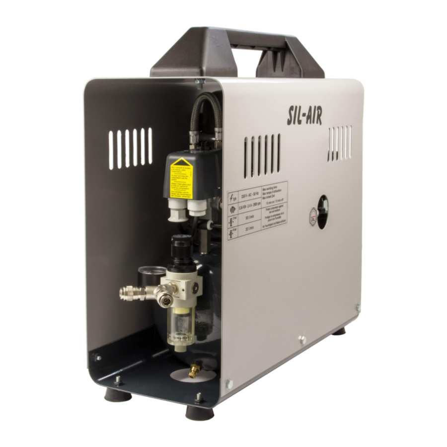
- Page 6 1.8 Main components 1.8 Hauptbestandteile 1 - Motor 1 - Motoaggregatr 2 - Lufttank 2 - Air tank 3 - Druckwächter 3 - Pressure switch 4 - Tankdruck-Manometer 4 - Tank pressure gauge 5 - Druckreduzierer/Filter 5 - Filter reducer 6 - Luftdrucmanometerk 6 - Outlet pressure gauge 7 - Sicherheitsventil...
-
Page 7: Technical Specifications
Model Volt/Hz Lt/min. dB(A)1m KW - AMP Modell 1ph ±10% C.F./min Gal. dB(A)40" 230/50 0,13 - 1 15 A 115/60 0,15 - 1,9 0,60 230/50 0,13 - 1 15 D 115/60 0,15 - 1,9 0,60 1,05 230/50 0,13 - 1... - Page 8 2.2 Air intake / pressure curves 2.2 Diagramme (Zuluft/Druck) MOTOR TYPE 15 MOTOR TYPE 50 MOTOR TYPE 30 MOTOR TYP 15 MOTORS TYP 50 MOTOR TYP 30 2.3 Wiring diagrams 2.3 Elektroschaltpläne Motors type 15 and 30 Motor type 50 - Motoren typ 50 Motoren typ 15 und 30 Relè...
- Page 9 Operation Betrieb 3.1 Machine set up 3.1 Aufstellung Install the compressor on a flat surface, in a Den Kompressor auf einer waagerechten suitably sized room, well ventilated and not Fläche in einem gut belüfteten, trockenen wet, where the temperature is not likely to Raum geeigneter Größe und mit einer Raum- rise above 35°C.
- Page 10 SPECIAL NOTE FOR THE MOTOR WARNUNG über 15 und 30 MOTOREN TYPE 15 AND 30 MACHEN SIE NICHT DIE NEVER PERFORM THE ÖLBEFÜLLUNG DURCH DIE OIL FILLING THROUGH SAUGLEITUNG,DIE IN DER THE SIDE PIPE, POSI- NäHE DER ELEKTRISCHE TIONED CLOSE TO ANSCHLUSS POSITIONIERT THE ELECTRICAL IST.
- Page 11 The pressure switch stops the compressor Der Druckwächter hält den Kompressor an, when the pressure in the tank reaches the wenn der Druck im Tank den Höchstwer t(8 maximum value allowed (8 bar¹120psi stan- bar¹120psi standard) erreicht und schaltet ihn dard) and starts it again when the wieder ein, wenn der Druck den pressure drop to the minimum value...
- Page 12 If the pressure switch does not work Wenn der Druckwächter bei Überdruck nicht (overpressure), the safety valve will auto- anspricht, schaltet sich das Sicherheitsventil matically operate and open when the pres- ein, das sich öffnet, wenn der Druck den maxi- sure exceeds the max.
- Page 13 3.3 Limits for continuous operation 3.3 Einschränkung des Dauerbetriebs Curve n°1 (fig.5) indicates the length of Die Kurve Nr. 1 zeigt den maximalen Dauer- · · betrieb bis za. 115° C Motortemperatur er- continuous running at varying pressures, reicht wird. (Ausschalttemperatur des Motor- until the overload protector switces off the schutzes) bei anfänglicher Motortemperatur motor (at approx.
- Page 14 3.5 Kontrolle der Befüllungszeit Filling up time of the tank from 0 to max. pressure (in seconds) Tankfüllungszeiten von 0 bis max.-Druck (in Sekunden) Compressor model: - Kompressormodell: Volt/Hz 15 A 15 D 15 TC 15 TDC 15 EXPORT A 30/4...
-
Page 15: Periodic Maintenance
Maintenance Wartung 4.1 Periodic maintenance 4.1 Regelmässig durchzuf. Wartung WARNING! ACHTUNG! All following operations, must be done by Alle diese Eingriffe dürfen nur von ausgebildetem Fachpersonal ausgeführt a specialised personnel. werden. once a once a once a week month year Einmal Einmal Einmal... - Page 16 4.2 Oil replacement 4.2 Oelwechsel Act as follows fig.10: Folgendermassen vorgehen, Abb. 10: 1. remove the motor unit from the tank, if 1. Wenn notwendig, Motor vom Tank demon- necessary. tieren; 2. remove the finned cover by loosing the 4 2.
-
Page 17: Troubleshooting
Troubleshooting Fehlersuche- und Behebung WARNING ACHTUNG! Before any operation on the compressor, Vor jedem Eingriff am Konpressor den Strom · · abschalten. disconnect the plug from the socket. Den Lufttank ganz ablassen, bevor beliebi- Empty air tank of air before dismantling ·... - Page 18 5.2 The compressor does not reach the 5.2 Der kompressor läuft, erreicht jedoch maximum pressure nicht den höchstdruck. a) Check any air leak (See point 5.6). a) Bitte die Anlage auf Undichtigkeit über- · · prufen (Vgl. Punkt 5.6). b) Check the pressure switch efficency and ·...
- Page 19 5.7 Leak from the valve placed under the 5.7 Leckage am Ventil unter dem pressure switch Drückwächter Damaged valve, replace it. a) Beschädigtes ventil; bitte anwechseln. · · b) Die Störung kann durch ein undichtes The defect can be due to an unperfect ·...
- Page 20 Special informations Zusatzinformationen 6.1 Compressor demolition 6.1 Entsorgung des Kompressors During the compressor demolition all Beim Verschrotten des Kompressors müssen alle erforderlichen Sicherheits- possible safety regulations must be ob- vorkehrungen getroffen werden, um Per- served in order to avoid any damage to sonen- und/oder Sachschäden zu vermei- people or things.
- Page 47 Denominacion Part Code Descrizione Description Beschreibung Description ECROU HAUT M4 UNI 5587 TUERCA M4 UNI 5587 ZB A0218 DADO ALTO M4 UNI 5587 ZB NUT M4 MUTTER M4 SCREW TE M8X16 UNI 5739 SCHRAUBE TE M8X16 UNI TORNILLO TE M8X16 UNI B0030 VITE TE M8X16 UNI 5739 ZB VIS TE M8X16 UNI 5739 ZB...
- Page 48 VERLÄNGERUNG M 1/4"÷ F DISTANCIADOR M 1/4"÷ F C0059 PROLUNGA M 1/4"÷ F 1/4" EXTENSION M 1/4"÷ F 1/4" RALLONGE M 1/4" - F 1/4" 1/4" 1/4" C0061 VITE TE M8X10 UNI 5739 SCREW TE M8X10 UNI 5739 SCHRAUBE VIS TH M8X10 UNI 5739 TORNILLO RONDELLA Ø10,5X21 UNI ARANDELA PLANA Ø10...
- Page 49 RONDELLA Ø8,4X17 UNI RONDELLE Ø8,4X17 UNI C0100 WASHER Ø8,4X17 UNI 6592 SCHEIBE Ø8,4X17 UNI 6592 ARANDELA Ø8 ZINCADA 6592 6592 C0101 COLLARE GRUPPO T2134A HOLDING BAND T2134A GUARNIZIONE PVC CON C0103 PVC GASKET HOSE DICHTUNG JOINT JUNTA FORI SECHSKANTSCHRAUBE TORNILLO TE M8X30 C0105 VITE TE M8X30 UNI 5739 SCREW TE M8X30 UNI 5739...
- Page 50 RIPARTITORE 5 VIE CROCE C0156 EXTENSION PIECE F 4X1/4-F 1X1/8 RUOTA GOMMATA D200 C0160 WHEEL D200 ROUE FORO 20 FILTER REGULATOR FR BIT C0164 RIDUTTORE FILTRO 1/4" REGLER FILTER 1/4" RÉDUCTEUR FILTRE 1/4" REDUCTOR FILTRO 1/4" 1/4" CAVO EL 3X1,6 AWG SPINA ELECTRIC CABLE 3X1.6 CÂBLE ÉLECTRIQUE AWG C0180...
- Page 51 OVERLOAD PROTECTOR C0317 RELÈ TERMICO T21 ( 115V ) RELAIS RELAIS RELÉ T21 ( 115V ) C0323 VALVOLA ASPIRAZIONE T21 INTAKE VALVE VENTIL SOUPAPE VÁLVULA VALVOLA COMPRESSIONE C0324 EXHAUST VALVE VENTIL SOUPAPE VÁLVULA RELÈ AVVIAMENTO T21 ( C0325 START RELAY T21 ( 115V ) RELAIS RELAIS RELÉ...
- Page 52 INSERTO MANIGLIA MOD. HANDLE INSERT MOD. C0414 EINSATZ INSERTO COMPACT COMPACT CAVO EL MM 600 (CODICE C0416 ELECTRIC CABLE MM 600 ELEKTR. KABEL MM 600 CÂBLE ÉLECTRIQUE CABLE C416) RONDELLA P 6X24 UNI 6592 C0431 WASHER SCHEIBE RONDELLE ARANDELA C0435XX CARENATURA 15-30D COWLING 15-30D GEHÄUSE 15-30D...
- Page 53 GRIGLIA PER VENTOLA LAUFRAD MIT GITTER VENTILATEUR AVEC REJILLA VENTILADOR C0664 FAN PROTECTION 120X120 120X120 120X120 GRILLE 120X120 120X120 VENTOLA A SCATOLA COOLING FAN 120X120 VENTILADOR 120X120 C0665 LAUFRAD 120X120 230/50 VENTILATEUR 230/50 120X120 230/50 230/50 230/50 REDUCTION M-F 1/4X 3/8 C0884 RIDUZIONE M-F 1/4"X3/8"...
- Page 54 TUBO ARIA MM235 1/8FX1/8F C1776 FLEX PIPE LUFTSCHLAUCH TUYAU AIR TUBO AIRE KIT FILTRO ASPIRAZIONE C1794 KIT INTAKE FILTER FILTERSET KIT FILTRE KIT FILTRO CORTO C1801XX GABBIETTA VENTILATORE FAN CAGE C1862 PIEDINO GOMMA RUBBER SUPPORT STÜTZFUSS PIED CAOUTCHOUC PIE DE GOMA ANELLO PROTEZIONE JOINT PROTECTION ANILLO PROTECTOR...
- Page 55 KIT PLACCA KIT VALVE PLATE+GASKET C2586 KIT PLATTEN KIT PLAQUE KIT PLACA VALVOLE+GUARNIZIONI L55 C2587 GUARNIZIONE CILINDRO L55 CYLINDER GASKET DICHTUNG JOINT JUNTA PLACCA VALVOLA L55 VALVE PLATE L55 WITH C2588 PLATTEN PLAQUE PLACA COMPLETA DI VALVOLE VALVE C2589 GUARNIZIONE TESTATA L55 HEAD GASKET DICHTUNG JOINT...
- Page 56 NOTE ..........................................................................................................................................................................................................................................................................................................................................................................................................................................................................................................................................................................................................................................................
Need help?
Do you have a question about the 15 A and is the answer not in the manual?
Questions and answers