
Summary of Contents for Light Wave JSJSLW920
- Page 1 Boiler Switch Model No. JSJSLW920 Instruction Manual Professional Series www.lightwaverf.com...
-
Page 2: Ec Declaration Of Conformity
Innovation Campus Birmingham Faraday Wharf Holt Street Birmingham B7 4BB Tel: +44 (0)121 250 3625 Email: enquiries@lightwaverf.com Model Number(s): JSJSLW920 Description: Boiler Switch Directives this equipment Complies with: 2006/95/EC The Low Voltage Directive N/A 2004/108/EEC The Electromagnetic Compatibility Directive 1999/5/EC R&TTE Directive... -
Page 3: How Do I Get Started
Get started How do I get started? To install the Boiler switch, please follow these instructions. You must also refer to the wiring instructions specific to your boiler type which can easily downloaded www.lightwaverf.com/product-manuals or by scanning the QR code below. The setup guide in these instructions will then explain how to link the Boiler Switch... -
Page 4: Front View
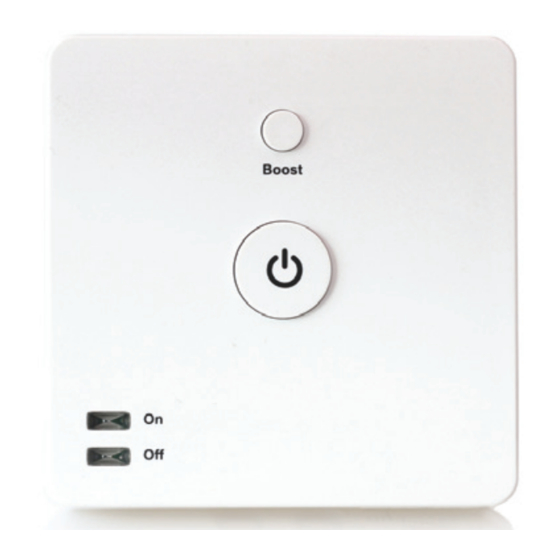
Quick Start Guide Installation Overview Front view Boost button. Temporarily Linking button. turns on boiler. Press to enter linking mode ‘On’ LED. When Standby button. illuminated Turns boiler boiler is on. on/o ‘O ’ LED. When illuminated boiler is o . IMPORTANT: All LightwaveRF products can be legally DIY installed in your own home;... - Page 5 Installation Rear view with backplate removed Tightening Hook Screws Cable clamp Wiring mount (clamp terminals removed) Cable hole (cover not Backplate removed) screw hole Close-up of wiring terminals IMPORTANT: If conducting an insulation resistance test, all LightwaveRF products must be disconnected from the mains, or damage will occur.
-
Page 6: Installation Preparation
Quick Start Guide Installation Installation preparation Key installation tools and materials Wire-cutters Flat-head Wire-strippers Cross-head screwdriver screwdriver Torch Sharp Knife Electrical tape 5 core cable IMPORTANT: If you are unsure about how to use any of these tools and materials, or any stage of the installation process, always consult a qualified electrician or heating engineer. -
Page 7: Safety Precautions
Installation Safety Precautions • Prior to installing the Boiler Switch, read through the wiring instructions provided thoroughly. Make sure that you understand your heating setup as specified on the following pages. • Before proceeding with the installation, check and ensure that the boiler is OFF and that no mains power is being received. - Page 8 Installation Remove the backplate and cable clamp Hook To gain access to the wiring terminals on the Boiler Switch, you must first remove the backplate. This can be done by loosening the two screws sited at the base of the unit using a suitable screwdriver.
- Page 9 Installation Understanding your heating setup To know where to install the Boiler Switch, you will need to know the type of heating setup that you have at home. Please identify your system and then refer to the corresponding section after this page. 1.
- Page 10 Quick Start Guide Install 1: combi boiler 1. Wiring to a standard combi setup (typical) The setup show below is a standard combi system which is common to most homes. Combi systems may or may not include a ‘room thermostat’ such as the one pictured.
- Page 11 Install 1: combi boiler Standard combi setup with LightwaveRF Boiler Switch The Boiler Switch replaces the original thermostat and is wired into the same room thermostat (RT) terminal. Unlike the original thermostat, however, it should now be located near the boiler, as it also needs to take incoming mains power from terminals located next to the room thermostat terminal.
- Page 12 Quick Start Guide Install 1: combi boiler Download your boiler manual from the support menu Standard combi boilers should all include the necessary connection points needed to wire the LightwaveRF Boiler Switch. However, these may be located di erently depending on the manufacturer. Please now locate and refer to the specific boiler manual for your make and model of boiler.
- Page 13 Install 1: combi boiler Access the boiler wiring centre The Boiler Switch needs to be wired to the room thermostat (RT) connection. In order to locate this, you must gain access to the boiler wiring centre inside the boiler. You should refer to your specific boiler manual to find out how to do this.
- Page 14 Quick Start Guide Install 1: combi boiler Locate the room thermostat (RT) terminal Once you have accessed the wiring centre, you need to locate the room thermostat terminals. You will need to refer to the main ‘PCB’ wiring diagram in your boiler manual. The connections should usually be marked as ‘room thermostat’, ‘RT’, or, in some cases, ‘temperature sensor’...
- Page 15 Install 1: combi boiler Locate mains power terminals The Boiler Switch also needs to take mains power from the boiler. This can be routed from live, neutral and earth terminals located in the wiring centre. You should refer to your boiler manual to locate them. The terminals are usually located next to or near to the ‘room thermostat’...
- Page 16 Quick Start Guide Install 1: combi boiler Wire the Boiler Switch Link the Boiler Switch and boiler terminals as shown in the diagram using the single 5 core cable. Remember that the terminal arrangement on your boiler may di er, so please refer to your specific boiler manual for guidance. ‘Normally open’, ‘common’...
- Page 17 Install 2: Y plan 2. Wiring to a Y plan heating system The basic diagram below shows the main constituent elements of a Y plan system which is common in larger houses. The system boiler produces hot water which is stored in the tank and/or circulated in the central heating system.
- Page 18 Quick Start Guide Install 2: Y plan Access the wiring centre The Boiler Switch needs to be wired in place of the existing room thermostat. In order to locate this connection, you must gain access to the system wiring centre. This is often located near to the hot water cylinder. Make sure that you turn o the mains power.
- Page 19 Install 2: Y plan Typical wiring for a Y plan setup Neutral connection Connecting wires Room thermostat (with neutral wire connection) to be replaced by Boiler Switch which requires additional live and earth connections.
- Page 20 Quick Start Guide Install 2: Y plan Wire the Boiler Switch Use a 5 core cable to connect the Boiler Switch to the wiring centre (you can also use a 2 core and a 3 core cable together instead). Connect the room thermostat terminals, and add live, neutral and earth as shown in the diagram.
- Page 21 Install 3: S plan 3. Wiring to an S-plan heating system The basic diagram below shows the main constituent elements of an S plan system which is common in larger houses. The system boiler produces hot water which is stored in the tank and/or circulated in the central heating system.
- Page 22 Quick Start Guide Install 3: S plan Access the wiring centre The Boiler Switch needs to be wired in place of the existing room thermostat. In order to locate this connection, you must gain access to the system wiring centre. This is often located near to the hot water cylinder. Make sure that you turn o the mains power.
- Page 23 Install 3: S plan Typical wiring for an S plan setup Neutral connection room thermostat connections Room thermostat (with neutral wire connection) to be replaced by Boiler Switch which requires additional live and earth connections.
- Page 24 Quick Start Guide Install 3: S plan Wire the Boiler Switch Use a 5 core cable to connect the Boiler Switch to the wiring centre (you can also use a 2 core and a 3 core cable together instead). Connect the room thermostat terminals, and add live, neutral and earth as shown in the diagram.
- Page 25 Install 4: Multi-zone (S plan plus) 4. Wiring to a multi-zone heating system The basic diagram below shows the main constituent elements of a multi-zone (S plan plus) system. This system resembles the S plan system (see previous section), but includes multiple motorised valves each controlling a heating zone.
- Page 26 Quick Start Guide Install 4: Multi-zone (S plan plus) Access the wiring centre A Boiler Switch needs to be wired in place of each existing room thermostat. In order to locate these connections, you must gain access to the system wiring centre.
- Page 27 Install 4: Multi-zone (S plan plus) Typical wiring for a multi-zone (S plan plus) setup Zone Zone valve 2 valve 1 Neutral connection Room thermostat 2 Connecting wires Connecting wires Room thermostat 1 (with neutral wire connection) to be replaced by Boiler Switch which requires additional live and earth connections.
- Page 28 Quick Start Guide Install 4: Multi-zone (S plan plus) Wire the Boiler Switch Use 5 core cables to connect each Boiler Switch to the wiring centre (you can also use two 2 core and two 3 core cables instead). Connect the room thermostat terminals, and add live, neutral and earth as shown in the diagram.
- Page 29 Installation Completing the Install Install the cable clamp Once the cable(s) have been connected, the cable clamp needs to be reattached in order to secure them and to ensure that they cannot become dislodged from the terminal connections. The cable(s) should run thorough holes situated at the base of Holes Clamp...
- Page 30 Quick Start Guide Installation Adjust your boiler settings complete control, important to ensure that it is the only LightwaveRF Boiler Switch that manages the on/o status of your boiler, and that it cannot be overridden another thermostatic control or separate Set to ‘always on’...
-
Page 31: Basic Operation
Manual Operation Basic Operation The Boiler Switch is designed to turn your boiler on and o . It is designed to be ‘linked’ to, and controlled by, the LightwaveRF Home Thermostat. The Boiler Switch will then automatically abide by the temperatures and schedules that you set from Thermostat. - Page 32 Manual Operation The Standby button Standby button If not connected to a Home Thermostat, pressing the Standby button on the Boiler Switch toggles the Boiler on and o . Once the Boiler Switch is linked to a Home Thermostat, pressing Standby will toggle between the set ‘on’...
- Page 33 Manual Operation The Boost button Pressing the Boost button on the Boiler Switch raises the target temperature several degrees above the current temperature for the duration of one hour. If the target temperature is already several degrees higher than the actual temperature, then pressing boost will simply match this temperature.
- Page 34 Device Setup Linking the Boiler Switch to the Home Thermostat In order to schedule your heating and to use the heating remotely, you will need to ‘link’ the Boiler Switch to the LightwaveRF Home Thermostat. The Boiler Switch can be linked to the Thermostat using the following method. Press and release the ‘Link’...
- Page 35 Add other Heating Devices Home Thermostat Boiler Switch Lightwave App (monitors house temp.) (turns boiler on/o ) (control any room from anywhere) Lounge Room Thermostat (controls several TRVs) Lightwave link Heating Remote (runs the show) (sets house temp.) Bedroom 2 Bedroom 1 Window Trigger (open window turns o TRV)
- Page 36 Heating Scenarios 1. (Intermediate): Remote control of the Boiler Required: Boiler Switch, Home Thermostat, Heating Remote It is really comfortable and convenient to be able to have direct control over the house temperature without having to get up and alter the thermostat or boiler.
- Page 37 Heating Scenarios 2. (Advanced): Zoned Heating Required: TRVs, Lightwave Link, Boiler Switch, Thermostat etc. With the LightwaveRF App and the Lightwave Link you can create an expandable zoned system that can take care of your entire home. Temperatures can be set for each room or ‘heating zone’, and heating can be planned week by week and room by room.
- Page 38 FAQs Heating System Setup Does the Boiler Radiator Switch have a ‘standby’ power comsumption? The Switch has a standby power consumption of approx. 0.5W. This is because the in-built radio receiver requires power in order to receive commands. This rate is low & well within government energy guidelines. Does the Boiler Switch have to work with a Home Thermostat? Yes.
- Page 39 Technical Specification Specification RF frequency: 868 MHz Input: 230V Output: 7 Amps Warranty: 2 year standard warranty...
- Page 40 Version 2 Innovation Birmingham Campus Faraday Wharf Holt Street Birmingham B7 4BB 01707 386035 www.lightwaverf.com...
Need help?
Do you have a question about the JSJSLW920 and is the answer not in the manual?
Questions and answers