Xray X12 Instruction Manual
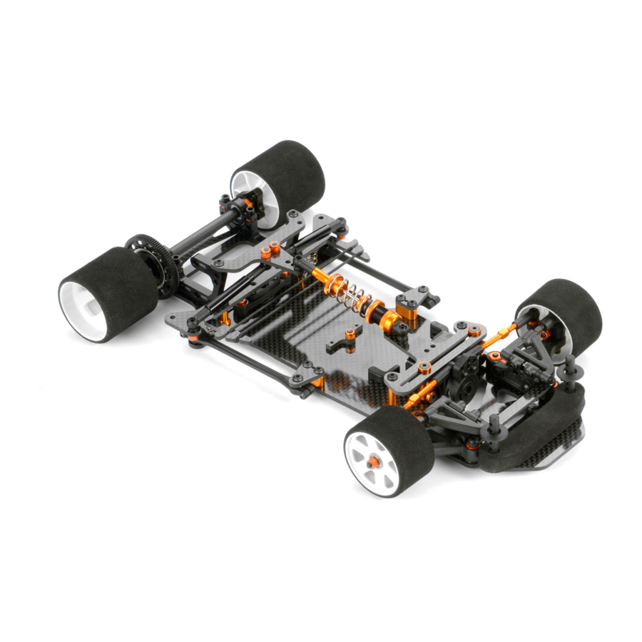
A high-quality, 1/12-pan car intended for persons aged 16 years and older with previous experience building and operating rc model racing cars
Hide thumbs
Also See for X12:
- Instruction manual (32 pages) ,
- Instruction manual (32 pages) ,
- Instruction manual (28 pages)
Table of Contents
Advertisement
Quick Links
Advertisement
Table of Contents

Related Manuals for Xray X12


Summary of Contents for Xray X12
- Page 2 Make sure you review this entire manual and examine all details carefully. If for some reason you decide the X12 is not what you wanted or expected, do not continue any further. Your hobby dealer cannot accept your X12 kit for return or exchange after it has been partially or fully assembled.
-
Page 3: Symbols Used
(here twice) movement EQUIPMENT INCLUDED TOOLS REQUIRED Diff. Grease Allen Wrench 1.5mm Allen Wrench 2.0mm Allen Wrench 2.5mm Socket Driver 5.5mm XRAY Premium (HUDY #111540) (HUDY #112040) (HUDY #112540) (HUDY #170055) (HUDY #106211) Silicone Oil 700cSt (#359270) & Silicone Oil 3000cSt... - Page 4 GRAPHITE PART PREPARATION PREPARE All GRAPhitE PARtS To protect and seal edges of graphite parts, sand edges smooth and then apply CA glue. Fine sandpaper Use fine sandpaper to sand smooth the edges of all graphite parts. Apply CA glue to all adges of the graphite parts.
-
Page 5: Front Suspension
C=5.0 - BLACK 965019 #372183 C=6.0 - GREY 371103 X12 LINK CHASSIS - 2.5MM GRAPHITE 372221 COMPOSITE STEERING BLOCK - LEFT - HARD 375220 FRONT WHEEL AXLE (2) 372010 COMPOSITE FRONT UPPER ARM MOUNT - RIGHT 372280 KING PIN (2) - Page 6 NOTE ORIENTATION 3x12 Marked “L“ STEEL BALL Lightly tighten setscrews REACtivE CAStER SEttiNG 5.2mm 5.2mm = 2.5° COMPOSITE BALL = 5° INITIAL SETTING = 7.5° Use same bushings in left and right sides. ASSEMBLED VIEW ASSEMBLED VIEW NOTE ORIENTATION ASSEMBLED VIEW CASTER CAMBER 902308...
- Page 7 VERY IMPORTANT The front suspension is manufactured from composite The flat of the nut must be PARAllEl to the lower arm. material which may slightly move or bend when the mounting screws are tightened. As such it is extremely important 1.
- Page 8 INITIAL SETTING 0.5mm After inserting clips, carefully tighten all M3x4 setscrews so the pins will not move. Do not overtighten or you may strip the plastic. Loosen all M3x4 setscrews so you If the arm does not have can easily remove the pins. enough play, remove the clips and thin the clips slightly with sandpaper.
-
Page 9: Rear Suspension
3. REAR SUSPENSION 378010 378140 tAPEREd SPRiNGS 902306 #373581 C=1.1 - SILVER 378150 #373582 C=1.4 - GOLD 902258 373082 #373583 C=1.7 - BLACK 901308 378010 303241 372650 372650 901310 371190 903306 902306 960031 306219 372650 960031 902306 373590 373542 306219 TAPERED 902306 SPRING... - Page 10 Lightly tighten the screws so there is no free play, but do not overtighten otherwise the pivotball will not move freely. 3x10 3x10 DO NOT TIGHTEN FULLY Ensure free, smooth movement without excessive freeplay. 903306 903310 902306 960031 903310 SFH M3x6 SFH M3x10 SH M3x6 ALU N M3...
- Page 11 DO NOT TIGHTEN FULLY, PIVOTBALLS MUST TURN FREELY. ASSEMBLED VIEW TIGHTEN FULLY 960031 903314 902258 903306 ALU N M3 SFH M3x14 SH M2.5x8 SFH M3x6...
- Page 12 3x6x2 3x6x2 0.5mm "CLICK" 306219 901308 902306 903306 960031 SHIM 3x6x2 SB M3x8 SH M3x6 SFH M3x6 ALU N M3...
- Page 13 3x6x1 3x6x1 902306 960031 306219 903306 902306 903308 SH M3x6 ALU N M3 SHIM 3x6x1 SFH M3x6 SH M3x6 SFH M3x8...
- Page 14 Add oil in each slot of the derlin side shock tubes. NOtE: add oil only in the slots, not on the whole tube. After assembling the side tubes, check for smooth operation. NOtE: It is very important to re-oil the side tubes, as least once per race day.
-
Page 15: Ball Differential
4. BALL DIffERENTIAL 960031 375050 375030 930130 963030 930138 941438 941438 375080 375010 375896 375080 375090 372070 375090 375040 951438 951438 908258 372070 COMPOSITE RIDE HEIGHT ADJUSTER SET (2) 908258 HEX SCREW SOCKET HEAD CAP M2.5x8 (10) 375010 REAR AXLE SHAFT - GRAPHITE 930130 CARBIDE BALL 3.175MM (12) 375030... - Page 16 Bearing Oil (HUDY #106230) Use additional shims to widen the rear track-width. Use the same shims on both sides. For initial assembly use 6.4x8.4x1mm shims. Bearing Oil Flanged (HUDY #106230) Flanged The axle must have a VERY small amount of Use these Ride Height sideplay.
- Page 17 3.2mm 3.0mm 8.0mm 7.8mm Diff Grease (HUDY #106211) Diff Grease NOTE (HUDY #106211) ORIENTATION NOTE ORIENTATION Bearing Oil Diff Grease (HUDY #106230) This nut affects the tightness and stiffness of the (HUDY #106211) NOTE rear differential. ORIENTATION Tighten the nut gently so the diff does not slip under power, but do not overtighten or damage Bearing Oil Diff Grease...
-
Page 18: Shock Absorber
5. SHOCk ABSORBER ShOCk SPRiNGS #378092 C=1.5 - SILVER #378093 C=1.8 - GOLD #378094 C=2.1 - BLACK 378010 378010 378050 378061 378080 965015 971022 378030 378020 SHOCK SPRING 901303 378010 ShOCk OilS #359210 100cSt #359250 500cSt #359215 150cSt #359255 550cSt 378040 #359220 200cSt... - Page 19 Carefully remove the shock piston from the frame, and remove all excess plastic flash Shock Oil Shock Oil ASSEMBLED VIEW 965015 971022 C 1.5 O 2x2...
- Page 20 dEFAult ShOCk SEttiNG FOR CENtER ShOCk ABSORBER Follow the steps below to set the shock. HALF TIGHTEN TIGHTEN FULLY 100% 700cSt 3~5x UP & DOWN ➐ Keep the shock shaft ➊ ➋ ➌ ➍ ➎ ➏ pushed in the shock body and tighten the shock cap Extend the shock shaft Move the shock shaft up and...
- Page 21 CENTER SHOCK ABSORBER INITIAL SETTING Press the collar FULLY onto the end of the shock shaft and tighten the M3x3 setscrew. For initial setting, thread fully. dOWNStOP AdjuStmENt The length of the shock absorber affects the amount ASSEMBLED VIEW of rear downstop. To adjust, thread the ball-joint on or off the threaded post on the bottom spring cap.
-
Page 22: Final Assembly
6. FINAL ASSEMBLY RECEIVER LiPo BATTERY (not included) (not included) SPEED CONTROLLER (not included) 306219 376310 STEERING SERVO 376255 (not included) 371320 301159 903310 376130 309400 903305 903305 372661 981210 372650 372610 372503 306219 372661 901303 902310 NOT INCLUDED 372503 375390 FROM SERVO NOT INCLUDED... - Page 23 We recommend using a servo Configuration for 1/12 pan cars. Left 3x6x2 for initial setting Configuration Right Servo (not included) 29mm NOTE from servo ORIENTATION Left thread Futaba Hitec KO Propo Note the orientation of The position of the servo depends on the servo saver when servo weight of the electronics.
- Page 24 NOTE ORIENTATION Note groove position NOTE 3x6x3 ORIENTATION Note groove position 902310 981210 903310 981210 306219 ACKERMANN SH M 3x10 P 2x10 SFH M 3x10 P 2x10 SHIM 3x6x3...
- Page 25 Receiver Speed controller Receiver wire Motor PiNiON GEARS Alu hARdCOAtEd (not included) (not included) (not included) #305968 18T / 64P (option) ➊ #305969 19T / 64P (option) #305970 20T / 64P (option) #305971 21T / 64P (option) Pinion (not included) #305972 22T / 64P (option) ➌...
- Page 26 Battery Pack (not included) Batteries have to be angled When inserting or removing the from the car. Fibre Tape (HUDY #107870) (not included) 903305 SFH M3x5...
- Page 27 NOT INCLUDED To ensure that you always have access to the most up-to-date version of the XRAY Set-up Book, XRAY will now be offering only the digital online version at our Web site at www.teamxray.com. By offering this online...
- Page 28 5 8 1 7 0 3 9 1 0 7 2 5...
Need help?
Do you have a question about the X12 and is the answer not in the manual?
Questions and answers