
Related Manuals for Thermal Dynamics Drag-gun


Summary of Contents for Thermal Dynamics Drag-gun
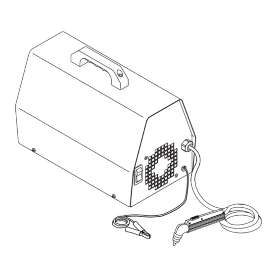
- Page 1 Plasma Cutting Power Supply Drag-gun A-03642 Service Manual November 11, 2003 Manual No. 0-2683...
- Page 3 While the information contained in this Manual represents the Manufacturer's best judgement, the Manufacturer assumes no liability for its use. Plasma Cutting Power Supply with Built-in Air Drag-Gun Service Manual Number 0-2683 Published by: Thermal Dynamics Corporation 82 Benning Street West Lebanon, New Hampshire, USA 03784 (603) 298-5711 www.thermal-dynamics.com Copyright 1999 by Thermal Dynamics Corporation All rights reserved.
-
Page 4: Table Of Contents
TABLE OF CONTENTS SECTION 1: GENERAL INFORMATION ....................1 1.01 Notes, Cautions and Warnings ................. 1 1.02 Important Safety Precautions ................1 1.03 Publications ..................... 2 1.04 Note, Attention et Avertissement ..............3 1.05 Precautions De Securite Importantes .............. 3 1.06 Documents De Reference ................ - Page 5 TABLE OF CONTENTS (Continued) 5.0 PARTS LIST ......................... 27 5.1 Returns ......................27 5.2 Parts Replacement ..................27 5.3 Power Supply Replacement Parts ..............28 5.4 Options & Accessories (not shown) ..............28 5.5 Torch Replacement Parts ................. 30 APPENDIX I - INTERCONNECTING DIAGRAM ................31 APPENDIX II - INTERCONNECTING DIAGRAM .................
-
Page 7: General Information
SECTION 1: GASES AND FUMES GENERAL INFORMATION Gases and fumes produced during the plasma cutting process can be dangerous and hazardous to your health. 1.01 Notes, Cautions and Warnings • Keep all fumes and gases from the breathing area. Throughout this manual, notes, cautions, and warnings Keep your head out of the welding fume plume. -
Page 8: Publications
• Wear dry gloves and clothing. Insulate yourself from the work piece or other parts of the welding PLASMA ARC RAYS circuit. • Repair or replace all worn or damaged parts. Plasma Arc Rays can injure your eyes and burn your skin. •... -
Page 9: Note, Attention Et Avertissement
6. ANSI Standard Z49.2, FIRE PREVENTION IN THE USE ATTENTION OF CUTTING AND WELDING PROCESSES, obtain- able from American National Standards Institute, 1430 Broadway, New York, NY 10018 Toute procédure pouvant résulter l’endommagement du matériel en cas de non- 7. AWS Standard A6.0, WELDING AND CUTTING CON- respect de la procédure en question. - Page 10 • Eloignez toute fumée et gaz de votre zone de respira- • Ne touchez jamais une pièce “sous tension” ou “vive”; tion. Gardez votre tête hors de la plume de fumée portez des gants et des vêtements secs. Isolez-vous provenant du chalumeau. de la pièce de travail ou des autres parties du circuit de soudage.
-
Page 11: Documents De Reference
ultra-violets très forts. Ces rayons d’arc nuiront à vos 1.06 Documents De Reference yeux et brûleront votre peau si vous ne vous protégez pas correctement. Consultez les normes suivantes ou les révisions les plus récentes ayant été faites à celles-ci pour de plus amples •... - Page 12 9. Norme 70 de la NFPA, CODE ELECTRIQUE NA- TIONAL, disponible auprès de la National Fire Pro- tection Association, Batterymarch Park, Quincy, MA 02269 10. Norme 51B de la NFPA, LES PROCÉDÉS DE COUPE ET DE SOUDAGE, disponible auprès de la National Fire Protection Association, Batterymarch Park, Quincy, MA 02269 11.
-
Page 13: Declaration Of Conformity
Rigorous testing is incorporated into the manufacturing process to ensure the manufactured product meets or exceeds all design specifications. Thermal Dynamics has been manufacturing products for more than 30 years, and will continue to achieve excellence in our area of manufacture. -
Page 14: Statement Of Warranty
The limited warranty periods for Thermal products shall be as follows (with the exception of XL Plus Series, CutMaster Series , Cougar and DRAG-GUN): A maximum of three (3) years from date of sale to an authorized distributor and a maximum of two (2) years from date of sale by such distributor to the Purchaser, and with the further limitations on such two (2) year period (see chart below). -
Page 15: Introduction
Department in West Lebanon for assistance. familiar with this equipment. 2.4 Technical Specifications Read this manual and the DRAG-GUN Operating Manual, 0-2682, thoroughly. A complete understanding of the ca- A. System Specifications pabilities and functions of the equipment will assure ob- taining the performance for which it was designed. -
Page 16: Dimensions
B. Input/Output Specifications Input Output Output Duty Model Amps Amps Voltage Cycle % (DC) (DC) 100/110V 50/60 25/24 120V * 120V 220V * 208/230V * CE approved. 2.5 Dimensions 10.0 in. (254 mm) A-02004 16.0 in 9.0 in (406 mm) (229 mm) Figure 2-1 Power Supply Dimensions 2.9 in... -
Page 17: Troubleshooting
6. Ground or work lead not connected Maintenance 3.4 Common Operating Problems The DRAG-GUN Operating Manual 0-2682, describes the Getting used to the way the system sounds and feels while inspection and maintenance procedures which should be it is operating properly will help to determine the nature performed at periodic intervals. -
Page 18: Troubleshooting Guide
NOTE fied amps. (Refer to Operator’s Manual 0-2682, sub- section 4.0-D for service amperage.) Although the DRAG-GUN will cut using standoff, • Use heavy gauge extension cords (Refer to Operator’s this unit is primarily a drag-cutting machine. Manual 0-2682, subsection 4.0-D for sizes). - Page 19 2. Damaged power cord. 4. Torch switch may have broken or shorted wires. a. Confirm with voltmeter if AC line voltage is a. Refer to subsection 3.6, Torch and Leads Trouble- present at input to power switch. shooting. If AC voltage is present, proceed to next step. 5.
- Page 20 G. Power OK, fan runs, compressor starts then shuts 7. Faulty Ferrite/Transformer Assembly. down as soon as the torch switch is pressed. a. The Ferrite Transformer Assembly is used to 1. Shorted, damaged, or incorrect torch parts. generate a high voltage pulse to establish the pilot arc.
-
Page 21: Torch & Leads Troubleshooting
If no continuity is found, check the resistance between the tion. Always wear light cutting gloves when chang- negative plasma lead fitting and the electrode seat in torch ing torch parts just after operating the Drag-Gun head. If no continuity is found, replace the torch and leads system. - Page 22 TROUBLE-SHOOTING Manual 0-2683...
-
Page 23: Replacement Procedures
List for the catalog number for a replacement power tion. Always wear light cutting gloves when chang- supply. ing torch parts just after operating the Drag-Gun • The torch head, torch switch, and torch & leads as- system. sembly are replaceable parts. The torch leads alone are not serviceable;... - Page 24 2. Install O-ring removed in step 8 above (L). 3. Optional: Install orange sleeving on replacement torch head gas input. Remove Six Screws 4. Place torch head in correct orientation, then insert lead cable into torch butt slice and crimp (M). 5.
-
Page 25: Torch Switch Only Replacement
Torch Switch Only Air Compressor Replacement Replacement NOTES NOTE Refer to subsection 4.1, General Information, for information about wire harnesses. This procedure requires the following tools (or equivalent): screwdriver, soldering iron, Flux. Refer to Appendix II for parts location and orienta- tion. -
Page 26: Capacitor Replacement
Replacement Transformer. 12. Install cover/handle by reversing steps in subsec- The DRAG-GUN Plasma Cutter has been manufactured using one of two styles of PC Board Assemblies. The tion 4.2, keeping in mind the following: Board will either have round mounting holes in the cor- a. -
Page 27: Power Relay Replacement
B. To Install Replacement PC Board: ON/OFF Power Switch Replacement 1. Install replacement key slotted PC Board by plac- ing PC Board over standoffs and sliding Board NOTE down into position. 2. Push a white fastener plastic push on into each When ordering a replacement ON/OFF Switch, order the same as found in your unit. -
Page 28: Fan Replacement
B. Model C: 4.10 Fan Replacement NOTE 1. Remove cover/handle from unit per subsection 4.2. Type C switch with 6 prongs replaces Type C switch with 4 prongs. 2. Carefully slide the Air Compressor out of the Trans- former bracket and out of the way of the Fan. Be 1. -
Page 29: Transformer/Ferrite Core Assembly Replacement
4.12 Transformer/Ferrite Core 4.13 Input Voltage Changeover (For Assembly Replacement 208/230 VAC Service Only) All 208/230 VAC units are factory set for 230 VAC. To switch to 208VAC input power operation, complete the WARNINGS following: Disconnect primary power at source before assem- WARNINGS bling or disassembling t he power supply. -
Page 30: Torch & Leads Replacement
5. Insert Torch leads through front hole on unit. 4.14 Torch & Leads Replacement 6. Slide Strain Relief Nut over the end of the torch 1. Remove cover/handle from unit per subsection 4.2. lead. 2. Disconnect the following (refer to Figure 4-4): 7. -
Page 31: Work Cable Replacement
4.15 Work Cable Replacement 4.16 Primary Input Power Cable Replacement 1. Remove cover/handle from unit per subsection 4.2. 1. Remove cover/handle from unit per subsection 4.2. 2. Disconnect the Work Cable Faston from mounting tab on bottom of Rectifier. 2. Disconnect Input Power Cable wiring to the ON/ OFF Switch and Ground. - Page 32 ON/OFF Input Power Switch Green Wire with Tracer (Connect to Compressor Frame) Strain Relief Primary Input Power Cable Green Wire Ground Stud (from Primary Input Power Cable) A-02653 Figure 4-7 Ground Connections 7. Connect the Ground Wires as shown. 8. Tighten Strain Relief. 9.
-
Page 33: Parts List
A. Complete Systems Includes Power Supply, PCH-10 70° Torch with Leads, Spare Consumable Parts, Input Power Cord, and Work Cable. DRAG-GUN 100V/50Hz 110V/60Hz, PCH-10 1-1111-3 DRAG-GUN 120V 50Hz, PCH-10, "CE" 1-1811-6 DRAG-GUN 120V 60Hz, PCH-10 1-1111-1 DRAG-GUN 220V 50Hz, PCH-10, "CE"... -
Page 34: Power Supply Replacement Parts
Work Cable, 15 ft. (4.57 m) w/Red Handles 9-0013 Input Power Cable, 6.5 ft. min. (2 m): DRAG-GUN 100V/50Hz 110V/60Hz, Power Cable, 14/3 w/molded plug 9-0052 DRAG-GUN 120V 50Hz, Power Cable, "CE", ** 9-0044 DRAG-GUN 120V 60Hz, Power Cable, 16/3 w/molded plug 9-0014 DRAG-GUN 220V 50Hz, Power Cable, "CE"... -
Page 35: Parts Lists
HARDWARE A Screw, #6-32 x 3 3/4 Lg, Phil Pan Hd, Zinc #6-32 Regular Nylon Lock Nut, Zinc Plated * For illustration purposes, the C 5/16-18 x 1 3/4 Unc Cap Socket Head Bolt Transformer/Inductor Assembly D 10-32 x .5 Pph Swageform Stl Zn. Parker Kalon E Screw, Black, 6-32 x 1/2 Pph, Swageform, Steel is shown separated from the F 10-32 Kepnut w/Star Washer Mild Steel... -
Page 36: Torch Replacement Parts
5.5 Torch Replacement Parts Item # Description Catalog# PCH-10 (70°) Torch Head Assembly* 9-0016 PCH-10 (180°) Torch Head Assembly* 9-0017 Torch Handle Only 9-0019 Torch Switch 9-1058 Standard Electrode 9-6006 PCH-10 Tip 9-6099 Gas Distributor 9-6007 Shield Cup 9-6003 Torch Head Split Holders PCH-10 (70°) 9-6259 PCH-10 (180°) -
Page 37: Appendix I - Interconnecting Diagram
APPENDIX I - INTERCONNECTING DIAGRAM NOTE: Use this diagram for all rev C units (or earlier). Check the data tag on the unit for rev level. Manual 0-2683 APPENDIX... -
Page 38: Appendix Ii - Interconnecting Diagram
APPENDIX II - INTERCONNECTING DIAGRAM A-02277 APPENDIX Manual 0-2683... - Page 39 NOTE: Use this diagram for all rev D (or later) units. Check the data tag on the unit for rev level. 12/01 8063 A-02277 Manual 0-2683 APPENDIX...
Need help?
Do you have a question about the Drag-gun and is the answer not in the manual?
Questions and answers