NEC MultiSync LCD1525V Service Manual
Hide thumbs
Also See for MultiSync LCD1525V:
- User manual (36 pages) ,
- Specifications (2 pages) ,
- Setup instructions (2 pages)
Table of Contents
Advertisement
Quick Links
See also:
User Manual
SERVICE MANUAL
COLOR MONITOR
MODELS LCD1525V (A) / (B)
This models changes an original model (LA-1527HMW (A) / (B) : product
made from NEC) into the product made from LITE-ON.
When the factory mark of a serial bar code label is "C", it is an original
model, and when a factory mark is "U", it is a model made from Lite-ON.
Refer to page 2-1 SERIAL NUMBER INFORMATION.
iLA-1527HMW: Factory mark: C
iLCD1525V :
MultiSync
Maintenance is performed by the original service manual
(Part No.599910487).
Factory mark: U
Maintenance is performed using this service manual.
NEC Corporation
PART NO. 599910514
LCD1525V
200004
08109388
08109389
Advertisement
Chapters
Table of Contents

Subscribe to Our Youtube Channel
Related Manuals for NEC MultiSync LCD1525V


Summary of Contents for NEC MultiSync LCD1525V
-
Page 1: Service Manual
MODELS LCD1525V (A) / (B) This models changes an original model (LA-1527HMW (A) / (B) : product made from NEC) into the product made from LITE-ON. When the factory mark of a serial bar code label is "C", it is an original model, and when a factory mark is "U", it is a model made from Lite-ON. - Page 2 WARNING The SERVICE PERSONNEL should have the appropriate technical training, knowledge and experience necessary to: • Be familiar with specialized test equipment, and • Be careful to follow all safety procedures to minimize danger to themselves and their coworkers. To avoid electrical shocks, this equipment should be used with an appropriate power code. This equipment utilized a micro-gap power switch.
- Page 3 CONTENTS Page No. USER'S MANUAL ------------------------------------------------------------------ 1-1 SERIAL NUMBER INFORMATION --------------------------------------------- 2-1 DISASSEMBLY ---------------------------------------------------------------------- 3-1 ADJUSTMENT PROCEDURES -------------------------------------------------- 4-1 INSPECTION --------------------------------------------------------------------------- 5-1 TROUBLE SHOOTING ------------------------------------------------------------- 6-1 CIRCUIT DESCRIPTION ----------------------------------------------------------- 7-1 REPLACEMENT PARTS LIST --------------------------------------------------- 8-1 BLOCK DIAGRAM ------------------------------------------------------------------ 9-1...
- Page 4 User's Manual Only the point is mentioned 1. A Version NEC LCD Series MultiSync MultiSync ® ™ 1525V ™ 1525V User’s Manual User’s Manual...
- Page 5 WARNING TO PREVENT FIRE OR SHOCK HAZARDS, DO NOT EXPOSE THIS UNIT TO RAIN OR MOISTURE. ALSO, DO NOT USE THIS UNIT'S POLARIZED PLUG WITH AN EXTENSION CORD RECEPTACLE OR OTHER OUTLETS UNLESS THE PRONGS CAN BE FULLY INSERTED. REFRAIN FROM OPENING THE CABINET AS THERE ARE HIGH VOLTAGE COMPONENTS INSIDE. REFER SERVICING TO QUALIFIED SERVICE PERSONNEL.
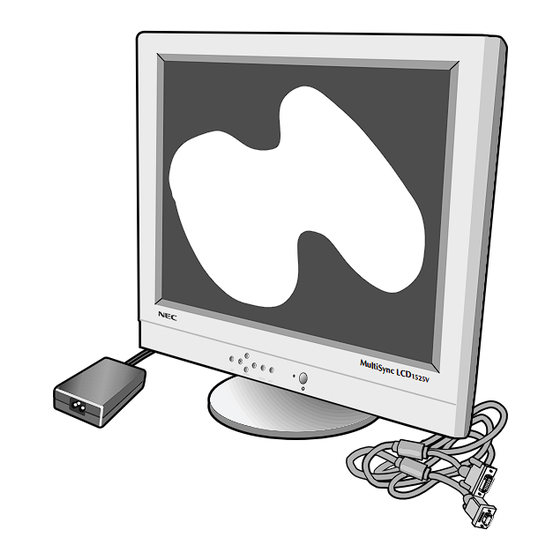
- Page 6 Contents You can register your product online at www.nectech.com/productregistration Your new NEC Technologies MultiSync LCD monitor box* should ® contain the following: • MultiSync LCD ™ 1525V monitor with tilt base • Power Cord • AC Adapter (#UP06051120) • Video Signal Cable •...
-
Page 7: Quick Start
NOTE: To obtain the MultiSync LCD Macintosh cable adapter, 1525V call NEC Technologies at (800) 820-1230. Remove connector cover and cable cover on back of monitor. 3. Connect the 15-pin mini D-SUB of the video signal cable to the appropriate connector on the back of the monitor (Figure C1). - Page 8 Quick Start cont. Figure C.1 Clip A Clip B Figure D.1 Power Switch Figure E.1...
- Page 9 Quick Start cont.
-
Page 10: Brightness And Contrast
Controls ™ (On-Screen-Manager) Controls The OSM controls on the front of the monitor function as follows: Control Main Menu Sub-Menu EXIT Exits the OSM controls. Exits to the OSM controls main menu. CONTROL Moves the highlighted Moves the highlighted area area up/down to select up/down to select one of the one of the controls. - Page 11 Controls cont. Controls AccuColor Control System ® Five color presets select the desired color setting. If a setting is adjusted, the name of the setting will change to Custom. Color Gain (Red, Green, Blue): Increases or decreases Red, Green or Blue color depending upon which is selected.
-
Page 12: Recommended Use
Recommended Use Safety Precautions and Maintenance FOR OPTIMUM PERFORMANCE, PLEASE NOTE THE FOLLOWING WHEN SETTING UP AND USING THE MULTISYNC LCD COLOR MONITOR: ® • DO NOT OPEN THE MONITOR. There are no user serviceable parts inside and opening or removing covers may expose you to dangerous shock hazards or other risks. - Page 13 Do not use primary color blue on a dark background, as it is difficult to see and may produce eye fatigue to insufficient contrast For more detailed information on setting up a healthy work environment, call NEC at (800) 820-1230, NEC FastFacts information at (630) 467-4363 and request ™...
-
Page 14: Specifications
Resolution based on horizontal and 800 x 600* at 56 Hz to 75 Hz vertical frequencies only 1024 x 768 at 60 Hz to 75 Hz ....NEC cites recommended resolution at 75 Hz for optimal display performance. Horizontal: 307 mm/12.1 inches... - Page 15 Multiple Frequency Technology: Automatically adjusts monitor to the display card’s scanning frequency, thus displaying the resolution required. Capability: Allows you to use the entire screen area in most resolu- FullScan ™ tions, significantly expanding image size. OSM Display Screen Copyright 1999 by NEC Technologies, Inc. 1-12...
-
Page 16: Troubleshooting
”ghost” of that image remains, the monitor should be turned off for one hour to erase the image. NOTE: As with all personal display devices, NEC Technologies recommends using a screen saver at regular intervals whenever the screen is idle. - Page 17 References • BBS (978) 742-8706 NEC Technologies’ Remote Bulletin Board System is an electronic service accessible with your system and a modem. Communication parameters are: 300/1200/2400/9600/14.4k/28.8k/33.6k bps, no parity, 8-data bits, 1 stop bit • Customer Service/ Technical Support (800) 632-4662 (978) 635-7049 •...
-
Page 18: Limited Warranty
Limited Warranty NEC Technologies, Inc. (hereinafter “NECTECH”), warrants this Product to be free from defects in material and workmanship and, subject to the conditions set forth below, agrees to repair or replace (at NECTECH’s sole option) any part of the enclosed unit which proves defective for a period of three (3) years from the date of first consumer purchase. -
Page 19: Why Do We Have Environmentally Labelled Computers
TCO'99 Congratulations! You have just purchased a TCO’99 approved and labeled product! Your choice has provided you with a product devel- oped for professional use. Your purchase has also contributed to reducing the burden on the environment and also to the further development of environmentally adapted electronics products. - Page 20 TCO'99 cont. accumulative* processes. Flame retardants have been found in human blood and researchers fear that disturbances in foetus development may occur. TCO’99 demand requires that plastic components weighing more than 25 grams must not contain flame retardants with organically bound chlorine and bromine. Flame retardants are allowed in the printed circuit boards since no substitutes are available.
- Page 21 monitor, using such applications as Microsoft Word, Excel or Paintbrush. To begin the setup/adjustment of the NEC MultiSync LCD monitor, 1525V push the Proceed button on the front bezel of the monitor to bring up the NEC On Screen Manager .
- Page 22 2. B Version User’s Manual 1-19...
- Page 23 Introduction to the NEC MultiSync LCD E - 1 1525V Introduction to the NEC MultiSync LCD 1525V Congratulations on your purchase of the NEC MultiSync LCD 1525V true colour monitor! Wider Compatibility Because the MultiSync LCD monitor is analog through and through, it does not require special analog to digital display or interface cards but can accept RGB input directly.
- Page 24 E - 2 Introduction to the NEC MultiSync LCD 1525V IPM (Intelligent Power Manager) System Provides innovative power-saving methods that allow the monitor to shift to a lower power consumption level when on but not in use, saving two- thirds of your monitor energy costs, reducing emissions and lowering the air conditioning costs of the workplace.
- Page 25 Contents E - 3 Contents Your new NEC MultiSync LCD monitor box should contain the following: MultiSync LCD monitor 1525V with video signal cable and AC Adapter Power Cord – NEC MultiSync LCD 1525V – AC Power Cord. – AC Adapter (Type. UP06051120).
- Page 26 E - 4 Recommended Use Recommended Use Safety Precautions and Maintenance For optimum performance, please note the following when setting up and using the MultiSync LCD colour monitor: • DO NOT OPEN THE MONITOR. There are no user serviceable parts inside and opening or removing covers may expose you to dangerous shock hazards or other risks.
- Page 27 Recommended Use E - 5 • AC Adapter shall not be used outdoors. • Handle with care when transporting. Save packaging for trans- porting. • The inside of the fluorescent tube located within the LCD moni- tor contains mercury. Please follow the bylaws or rules of your local municipality to dispose of this tube properly.
- Page 28 E - 6 Recommended Use CORRECT PLACEMENT AND ADJUSTMENT OF THE MONITOR CAN REDUCE EYE, SHOULDER AND NECK FATIGUE. CHECK THE FOLLOWING WHEN YOU POSITION THE MONITOR: • For optimum performance, allow 20 minutes for warm-up. • Adjust the monitor height so that the top of the screen is at or slightly below eye level.
- Page 29 Installation E - 7 Installation To attach the MultiSync LCD monitor to your system, follow these 1525V instructions: 1. Turn off the power to your computer. 2. For the PC: Connect the 15-pin mini D-SUB of the appropriate signal cable to the connector of the display card in your system (Figure A.1).
- Page 30 E - 8 Installation 15-pin mini D-SUB 15-pin mini D-SUB Mac Adapter (not included) Figure A.1 Figure B.1 1-27...
- Page 31 Installation E - 9 Figure C.1 Clip A Clip B Figure D.1 Power Button Figure E.1 1-28...
- Page 32 E - 10 Installation 1-29...
- Page 33 Controls E - 11 Controls OSM Controls The OSM controls on the front of the monitor provide the following functions: To access OSM press any of the control buttons ( ) or the PROCEED button. Main Menu Sub-Menu EXIT Exits the OSM controls. Exits to the OSM main menu.
- Page 34 E - 12 Controls Brightness and Contrast Brightness Adjusts the overall image and background screen brightness. Contrast Adjusts the image brightness in relation to the background. Auto Adjust Corrects the image displayed for non-standard video inputs. Auto Adjust Automatically adjusts the Position, H. size and Fine controls.
- Page 35 Controls E - 13 Auto Adjust Automatically adjusts the H. Size or Fine settings. Colour Control System Five options select the desired colour setting. If a setting is adjusted, the name of the setting will change to Custom. Colour Gain (Red, Green, Blue): Increases or decreases Red, Green or Blue colour depending upon which is selected.
- Page 36 E - 14 Controls Factory Preset Selecting Factory Preset allows you to reset all OSM control settings back to the factory settings. The RESET button will need to be held down for several seconds to take effect. Individual settings can be reset by highlighting the control to be reset and pressing the RESET button.
- Page 37 Specifications E - 15 Specifications Display 38 cm (15.1 inch) viewable image size; 1024 x 768 native resolution (Pixel Count); active matrix; thin film transistor (TFT); liquid crystal display (LCD); 0.30 mm dot pitch; 200 cd/m white luminance, typical; 200:1 contrast ratio, typical Analog 0.7 Vp-p 75 Ω...
- Page 38 E - 16 Specifications Power Supply AC 100-240 V @ 50/60 Hz Current Rating 0.6 A @ 100-120 V / 0.3 A @ 220-240 V Dimensions 370 mm (W) x 325 mm (H) x 151 mm (D) Weight 4.1 kg Operating Temperature 5°...
- Page 39 “ghost” of that image remains, the monitor should be turned off for one hour to erase the image. NOTE: As with all personal display devices, NEC recommends using a screen saver at regular intervals whenever the screen is idle.
- Page 40 E - 18 Troubleshooting/Support Problem Check These Items Image is unstable, - Signal cable should be completely attached to the unfocused or computer. swimming is - Use the OSM Image Adjust controls to focus and adjust apparent display by increasing or decreasing the Fine Control. When the display mode is changed, the OSM Image Adjust settings may need to be re-adjusted.
- Page 41 App. A PIN ASSIGNMENTS A - 1 App. A PIN ASSIGNMENTS MINI D-SUB 15 P Pin No. 1525V GREEN BLUE NO-CONNECTION GROUND GROUND GROUND GROUND +5V (DDC) GROUND GROUND H.SYNC, H/V.SYNC V.SYNC 1-38...
- Page 42 A - 2 App. B Preset Signal Timing App. B Preset Signal Timing Preset Resolution Vertical Horizontal Pixel Frequency (Hz) Frequency (kHz) Frequency (MHz) 640 x 400 56.42 24.83 21.05 640 x 480 59.99 31.47 25.18 720 x 350 70.09 31.47 28.32 720 x 400...
- Page 43 Auto Adjust your MultiSync LCD monitor. Display a white background with a bright image at full page setting on the monitor, using such applications as Microsoft Word, Excel or Paintbrush. To begin the setup/adjustment of the NEC MultiSync LCD monitor, 1525V push the Proceed button on the front bezel of the monitor to bring up the NEC On Screen Manager .
-
Page 44: Serial Number Information
SERIAL NUMBER INFORMATION Refer to the serial number information shown below. EX.) SERIAL BER CODE LABEL MODEL : LCD1525V SERIAL NO. : g g g g g g g g g Manufactured Year : ( Last digit ) Manufactured Month : January to September 1 to 9 October... - Page 45 DISASSEMBLY g Before you disassemble the set, turn off power and pull out the power plug. g Use the proper screwdriver. If oversize or undersize screwdriver is used, screws may be damaged. g Disassembly is the opposite process of assembly. Screw(A) Cover Cable AC Adapter...
- Page 46 Screw(B) Screw(C) Photo 2 * HOOK Photo 3...
- Page 47 Screw(D) Screw(E) FUNCTION P601 BD ASSY Photo 4 Screw(E) Screw(E) Photo 5...
- Page 48 Screw(E) P306 Screw(E) P305 P309 P308 INTERFACE BD ASSY Screw(G) INVERTER DC-AC 12V Screw, Special(HEX) Photo 6...
-
Page 49: Adjustment Procedures
ADJUSTMENT PROCEDURES TABLE OF CONTENTS Page 1. Preparations for Adjustment .................. 4-2 1.1 Measuring equipment used ................. 4-2 1.2 Power-supply voltage ..................4-2 1.3 Aging ........................4-2 1.4 Input Signal ......................4-2 2. Set Adjustment ...................... 4-2 2.1 Power supply turn-on ................... 4-2 2.2 Adjustments ...................... - Page 50 1. Preparations for Adjustment 1.1 Measuring equipment used Pre-programmed signal generator VG-819 (Astro Design) or equivalent product 1.2 Power-supply voltage AC 120 V ± 5%, 50/60Hz or AC 220 V ± 5%, 50/60Hz 1.3 Aging Unnecessary 1.4 Input Signal Input signal 20 (*1) from the video signal generator VG-819 with an inspection ROM device mounted. *1 For more details about the signals, see Section 3, "VG-819 Setting Method."...
- Page 51 2.2.2 Contrast adjustment 1) Use the VG-819 and enter Signal 20, in order to obtain a 16 gray pattern display. 2) Open the service menu. (See 2.2.1 herein.) 3) Using the 3 and 4 keys, select Tag 2 of the service menu and provide a display of the [AUTO OFFSET, AUTO CONT MAX] screen.
- Page 52 3. VG-819 Setting Method VG-819 setup VG-819 Mode Signal 20 DOT CLOCK [MHz] 78.75 TOTAL [DOT] 1312 DISP [DOT] 1024 SYNC PULSE [DOT] BACK [DOT] Hdstrat [DOT] Hdwidth [DOT] INTERLACE TOTAL [H] DISP [H] SYNC PULSE [H] BACK PORCH [H] EQPfp [H] EQPbp [H] SERRATION [H]...
- Page 53 INSPECTION 1. Inspection of PLUG & PLAY communication 1.1 A construction of System This system should be connected as shown below. * * * * T E S T P R O G R A M P ro g ram Dis k ...
- Page 54 1.3 Operation • The operation should be performed according to the screen message. • When the message of “Please set V. sync to 42Hz.” is displayed, set the signal generator to the signal with vertical synchronization frequency of 42Hz. When the message of “Please set V. sync to over 55Hz.” is displayed, set the signal generator to the signal whose vertical synchronization frequency is between 55Hz and 25kHz.
- Page 55 1.5 EDID data file The EDID data file text is shown below. When you write or inspect EDID for this monitor, the following table can be used. file name : LCD1525V EDID-128 Table 1.5 Data list (Management number : EDID-128) Week of manufacture = Month of manufacture ×...
- Page 56 2. Appearance of LCD and Display inspection standard 2.1 Dot defect 2.1.1 Bright Dot Bright dot is defined as dots(sub-pixels) which appeared brightly in the screen when the LCM displayed with dark pattern. • R, G or B 1 dot ---------------------------- 6 Max.
- Page 57 2.3 Foreign Material Items Criteria 0.05 ≤ W ≤ 0.1, 0.3 ≤ L ≤ 4, N ≤ 4 Linear Foreign 0.2 ≤ D ≤ 0.5, N ≤ 6 Material Circuar NOTE: D: Average Diameter D=(a+b)/2 W: Width, L: Length, N: Quantity Linear: a>2b, Circular: a<2b Unit: mm...
- Page 58 3. BACK LIGHT REPLACEMENT MANUAL TFT Color Liquid-crystal Module [LM151X2 (Part No. 36804268)] CONTENTS 1. Back light Replacement Procedure 1.1 Equipment and Tool Required for Replacement 1.2 Preparation 1.3 Replacement procedures Note: The replacement of the backlight tube in LCD module will not be reflected to extend the warranty period of whole LCD module or that of whole LCD monitor.
- Page 59 1. Back light Replacement Procedure 1.1 Equipment and Tool Required for Replacement 1) Finger protectors 2) ESD wrist strap 3) Precision Screw driver (+) 4) Replacement lamp unit Back light unit (Part No. 79PG1000) Recommendations: If or dirt adheres to the fluorescent lamp during replacement, it could result in uneven lighting, so it is recommend that replacement be performed in a clean room or on a clean bench (class C).
- Page 60 1.3 Replacement procedures To be explained according to the sequence of replacement work. (1) Put the TFT-LCD module on the working table, with its display plane facing upwards. Photo 1 (2) A screw is removed. Photo 2...
- Page 61 (3) Slowly pull the bracket, back light and take out the back light unit. Photo 3 Photo 4 (4) Then, take out the lower-side back light unit. Turn the LCD module upside down and follow the procedures (2) to (3). (5) Photo 5 shows the condition that the two upper and lower lamp units have been dislodged.
- Page 62 (6) Stand the LCD module and insert the back light unit. Photo 6 h Make sure not to confuse the direction of insertion. (7) After the completion of insertion, the back light unit is fixed with the screw. Photo 7 (8) Insert another back light unit according to the procedures of (6) and (7) above.
-
Page 63: Table Of Contents
TROUBLE SHOOTING TABLE OF CONTENTS page 1. No display of screen(Screen is black ,color of LED is amber) ........6-2 2. Nothing displays on screen(Screen is black ,color of LED is green) .......6-3 3. Checking the back light unit .....................6-6 4. Abnormal screen ......................6-7 5. -
Page 64: No Display Of Screen(Screen Is Black ,Color Of Led Is Amber)
1. No display of screen (Screen is black, color of LED is amber) Does OSM display when you push PROCEED button. When a signal isn't being Pressed "No OSM display" section. inputted, it is indicated with "VIDEOINPUT". It is indicated with "OUT OF RANGE"... -
Page 65: Nothing Displays On Screen(Screen Is Black ,Color Of Led Is Green)
2. Nothing displays on screen (Screen is black, color of LED is green) Is backlight lit? Refer "Checking the backlight unit" section Does computer output Check the video cable for failure. RGB video signals? Check the host for output signal with all black only. - Page 66 Continue Check the 3.3 V power are supplied on I103 pin 2. Check if the voltage on I103 pin3 that is high level DC at 5V. Failure point 1) Printed wire broke between I102 and I103 2) I102 failure. Failure point I103 Failure Is a dot clock being outputted under the condition that a LCD module is connected to...
- Page 67 Continue Check the data enable of positive polarity are output on P305 pin 42. Failure point 1) I401 failure 2) Printed wire broke between I401 and P305 pin 42. Check the data signal output on P305 R, G, B data pin. Failure point 1) I401 failure 2) Printed wire broke between I401 and P305 data line...
-
Page 68: Checking The Back Light Unit
3. Checking the back light unit Is +12V supplied to I101 pin 1 and pin 2, 3. Are connected AC adapters normal goods? Failure point Is +12V supplied to P309 pin 3, 4 to An AC adapter is changed to the inverter PWB? normal goods. -
Page 69: Abnormal Screen
4. Abnormal screen Check the R, G, B video signal from computer input on D-Sub R, G, B connector. Failure point 1) No R, G and B video signal output from host computer. Check computer 2) Video signal cable disconnection. Check the R, G, B input signals on I401 pin C13, C15 &... - Page 70 Continue Check the negative vertical sync pulse output to P305 pin 40 from I401 pin E20 at TTL level. Failure point 1) Printed wire broke between I401 pin E20 and P305 pin 40. 2) R315 open 3) C356 short Check the positive DE pulse output to P305 pin 42 from I401 pin T17 at TTL level.
-
Page 71: No Osm Display
5. No OSM display Check the output of 5Vp-p pulse from I402 pin 12, 13, 15, 17 when press PROCEED key. Check the input of 5Vp-p pulse from I402 pin 4, 5, 6. Check the output of 5Vp-p pulse from I208 pin 4, 5, 6. Proceed "Checking the operation of CPU"... - Page 72 Proceed "Checking the resolution change IC movement" section. Check the +5V is supply on I402 pin 8, 20. Failure point 1) C476 or C477 short. 2) I102 failure 3) Disconnection between I102 pin 2 and I402 pin 8, 20 may have failed. Check the input of the dot clock on I402 pin 7 at TTL level.
-
Page 73: Abnormal Auto Adjustment
6. Abnormal Auto adjustment Check the input of 3.3Vp-p pulse from I401 pin C11, C10, B11, A11, B10, A10 Failure point 1) Printed wire broke between I401 pin B11 and I201 pin2. 2) Printed wire broke between I401 pin A11 and I201 pin3. 3) Printed wire broke between I401 pin B10 and I201 pin4. -
Page 74: Abnormal Plug And Play Operation
7. Abnormal plug and play operation 7.1 Abnormal DDC1 Confirm the output of serial data on I403 pin 7 synchronize VCLK at TTL level. Failure point 1) This mode may be in DDC2B If you change the mode of DDC1, turn off the power switch of the host and the monitor and power again. -
Page 75: Checking The Interface Circuit Of Sync Signal
8. Checking the interface circuit of sync signal 8.1 Checking the control circuit of horizontal sync pulse Check the horizontal sync signal on I401 pin A1 TTL level. Failure point 1) Video cable may have failed. 2) Printed wire broke between P303 pin 13 and I401 pin A1 3) FB402, R437 open Process "Checking the resolution change IC movement"... -
Page 76: Checking The Resolution Change Ic Movement
9. Checking the resolution change IC movement Is there +3.3V supply on I401 pin A19, B20, C2, D6, D8, D10, D11, D12, D19, D20, F3, F4, G17, H3, J3, J4, K4, K17, L17, M17, N4, N17, P4, U6, U8, U9, U11, U13, U14 and V17 Proceed "Checking the DC/DC converter circuit"... -
Page 77: No Power On
10. No power on Check the +12V power is supplied from AC adapter. Failure point AC adapter failure. Is LED turned on in amber momentarily when a power button is pushed? Failure point Fuse failure. Check if TTL "H" level is input to Q102-base. Failure point D101, Q101, R101, R102 circuit Proceed "Checking the operation of CPU". -
Page 78: Checking The Dc/Dc Converter Circuit
11. Checking the DC/DC converter circuit Check if the 5V is output from I102 pin 2. Check if TTL "H" is output from Q102-base. Q101, D101, R101, R102 circuit. Check if the 12V is output from I101 pin 5,6,7,8. I101 failure. Check the input of 12V to the I102 pin1. -
Page 79: Checking The Operation Of Cpu
12. Checking the operation of CPU Is there +5.0V supply on I201 pin 44 Failure point Printed wire broke between output of FB106 and I201 power supply pin. Is 20MHz clock input to I201 pin 20 and 21 at TTL level? Failure point X201 failure. - Page 80 CIRCUIT DESCRIPTION TABLE OF CONTENTS Page 1. Power supply ......................7-2 2. On-screen circuit ......................7-2 3. Video input circuit .......................7-2 4. Definition converter LSI peripheral circuit ..............7-2 5. System reset,LED control circuit ................7-2 6. E PROM ........................7-2 7. CPU circuit .........................7-3 7.1 Dection of POWER switch status ................7-3 7.2 Display mode identification ..................7-3 7.3 User control ......................7-6...
-
Page 81: Power Supply
1. Power supply 1. I/02:DC-DC converter A 5V power supply for LCD module, CPU, and logic is generated from the 12V source. 2. I/03:3-terminal regulator A 3.3V power supply for LCD module is generated from the 5V source. 3. I/03:3-terminal regulator A 3.3V power supply for IC14 analog is generated from the 5V source. -
Page 82: Cpu Circuit
7. CPU circuit I201 (80C51RA2) functions as the CPU. The source voltage for the device is 5.0V and the system clock frequency 20MHz. 7.1 Detection of POWER switch status The CPU identifies the ON status of the two power supplies. The identification is made when the power supply is turned off. - Page 83 (4) Power save mode. The power save mode is assumed when the horizontal/vertical signals are as specified below. • If there is no horizontal sync signal input. • If there is no vertical sync signal input. • If the horizontal sync signal is outside the measuring range of B135. •...
- Page 84 Table 2. the number of the lines, Vsync distinction Indication resolution The number of the Distinction Vsync The fixed mode distinction lines The mode of 400 line and LINE≤487 FV≤63Hz under 63Hz<fV≤78Hz 78Hz≤fV 640×480 487<LINE≤607 FV≤63Hz 63Hz<fV≤68Hz 68Hz<fV≤74Hz 74Hz<fV≤78Hz 78Hz≤fV 800×600 607<LINE≤777 FV≤58Hz...
-
Page 85: User Control
7.3 User Control 7.3.1 Related ports of I401 Port Pin No. I/O Signal name Function Remarks The set value is returned to the initial MFB1 RESET RESET switch input value MFB10 EXIT EXIT switch input Withdraw from OSD 6 switch input MFB8 DOWN (6) key... -
Page 86: Power On Sequence
7.6 Power ON sequence When the POWER switch is pressed, the POWER OFF signal is turned “H”. When this “H” potential is detected, the CPU begins to establish the respective power supplies according to the sequence shown below. 500ms or more Indication is started 300ms or more POWER OFF... -
Page 87: Power Off Sequence
7.7 Power OFF sequence When the POWER switch is pressed while the power supply is ON, the POWER ON signal is turned “H”. When this “H” potential is detected, the CPU begins to turn off the respective power supplies according to the sequence shown below. - Page 88 7.8 List of CPU Pin Assignments Port Pull Signal Function Remarks Destina-tion name Vss1 Optional GRD P1.0 HDATA0 B135 Serial Data Data I/O terminal for communication P1.1 HDATA1 B135 Serial Data Data I/O terminal for communication P1.2 HDATA2 B135 Serial Data Data I/O terminal for communication B135 P1.3...
- Page 89 8. Inverter Protective circuit for back light and power source circuity This unit operates on an output voltage of 12V from AC adapter. When an AC adapter with an output voltage over 12V higher is connected, the control signal from I101 is forcibly connected to the LOW level through D101 (RLZ18B), Q101 (SST33904), and R101, R102.
-
Page 90: Replacement Parts List
REPLACEMENT PARTS LIST The components specified for Model LCD1525V(A) SYMBOL PART NO DESCRIPTION *** ICS *** I101 79PL1041 IC SI4431DY 8P SOP I102 79PL1040 IC LM2596S-5.0 TO-263(S) I103 79PL1145 IC RC1587M33 3P TO263 I104 79PL1038 IC LM358DR 8P SOP SMD I201 79PL1050 IC TS80C51RA2 44P PLCC... - Page 91 79PL1096 SW TACT TSAD-1 *** PWB ASSYS *** 79PL1122 INVERTER DC-AC 12V AA17 79PL1120 INTERFACE BD NEC-DL151AT AA19 79PL0952 FANCTION KEY BD NEC-DC150 79PL1121 PANEL BD NEC-DL151(99) *** COILS & FILTERS *** FB101 79PL1064 BEAD COREHB-1P4516-600T60 FB102 79PL1064 BEAD COREHB-1P4516-600T60...
- Page 92 F101 79PL1131 FUSE SLOW TR5-T 2.5A PC01 79PL0963 POWER CBL 1800GRY WALL 79PL1115 ADAPTER AC-DC 12V/4A WHIT V001 79PL0962 VIDEO CBL 1800 NEC-GRAY V002 79PL1134 FFC 45P 0.5 2896(ATYPE) X201 79PL1053 CRYSTAL 20MHZ HC-49/US X401 79PL1054 OSCILLTOR 50MHZ *** KNOBS & PUSH BUTTONS ***...
- Page 93 SYMBOL PART NO DESCRIPTION Y001 79PL1127 NEC C150ATA MANUAL ASSY *** RESISTORS *** R101 79PL1005 CHIP-R 4.7KH 1/8W J R102 79PL1005 CHIP-R 4.7KH 1/8W J R103 79PL1007 CHIP-R 51KH 1/8W J 805 R104 79PL1007 CHIP-R 51KH 1/8W J 805 R105...
- Page 94 SYMBOL PART NO DESCRIPTION R418 79PL1000 CHIP-R 150H 1/8W J 805 R419 79PL1000 CHIP-R 150H 1/8W J 805 R420 79PL1000 CHIP-R 150H 1/8W J 805 R421 79PL1000 CHIP-R 150H 1/8W J 805 R422 79PL1000 CHIP-R 150H 1/8W J 805 R423 79PL1000 CHIP-R 150H 1/8W J 805 R424...
- Page 95 SYMBOL PART NO DESCRIPTION C105 79PL1030 MC 0.1UF 50V Y5V Z SMD C106 79PL1030 MC 0.1UF 50V Y5V Z SMD C107 79PL0184 ALU UF 470 16V T 105C 10 C108 79PL1030 MC 0.1UF 50V Y5V Z SMD C109 79PL1023 MC 330PF 50V NPO J SMD C110 79PL1023 MC 330PF 50V NPO J SMD...
- Page 96 SYMBOL PART NO DESCRIPTION C306 79PL1022 MC 33PF 50V NPO J SMD C307 79PL1022 MC 33PF 50V NPO J SMD C308 79PL1022 MC 33PF 50V NPO J SMD C309 79PL1022 MC 33PF 50V NPO J SMD C310 79PL1022 MC 33PF 50V NPO J SMD C311 79PL1022 MC 33PF 50V NPO J SMD...
- Page 97 SYMBOL PART NO DESCRIPTION C423 79PL1026 MC 5PF 50V NPO J SMD C424 79PL1026 MC 5PF 50V NPO J SMD C425 79PL1030 MC 0.1UF 50V Y5V Z SMD C429 79PL1030 MC 0.1UF 50V Y5V Z SMD C430 79PL1020 MC 100PF 50V NPO J SMD C431 79PL1020 MC 100PF 50V NPO J SMD...
- Page 98 SYMBOL PART NO DESCRIPTION C474 79PL1024 MC 47PF 50V NPO K SMD C475 79PL1142 MC 1UF 16V Y5V M SMD C476 79PL1030 MC 0.1UF 50V Y5V Z SMD C477 79PL1030 MC 0.1UF 50V Y5V Z SMD C478 79PL1030 MC 0.1UF 50V Y5V Z SMD C479 79PL1030 MC 0.1UF 50V Y5V Z SMD...
- Page 99 REPLACEMENT PARTS LIST The components specified for Model LCD1525V(B) SYMBOL PART NO DESCRIPTION *** ICS *** I101 79PL1041 IC SI4431DY 8P SOP I102 79PL1040 IC LM2596S-5.0 TO-263(S) I103 79PL1145 IC RC1587M33 3P TO263 I104 79PL1038 IC LM358DR 8P SOP SMD I201 79PL1050 IC TS80C51RA2 44P PLCC...
- Page 100 79PL1096 SW TACT TSAD-1 *** PWB ASSYS *** 79PL1122 INVERTER DC-AC 12V AA17 79PL1120 INTERFACE BD NEC-DL151AT AA19 79PL0952 FANCTION KEY BD NEC-DC150 79PL1121 PANEL BD NEC-DL151(99) *** COILS & FILTERS *** FB101 79PL1064 BEAD COREHB-1P4516-600T60 FB102 79PL1064 BEAD COREHB-1P4516-600T60...
- Page 101 F101 79PL1131 FUSE SLOW TR5-T 2.5A PC01 79PL0971 POWER CBL 1900GRY WALL 79PL1115 ADAPTER AC-DC 12V/4A WHIT V001 79PL0962 VIDEO CBL 1800 NEC-GRAY V002 79PL1134 FFC 45P 0.5 2896(ATYPE) X201 79PL1053 CRYSTAL 20MHZ HC-49/US X401 79PL1054 OSCILLTOR 50MHZ *** KNOBS & PUSH BUTTONS ***...
- Page 102 SYMBOL PART NO DESCRIPTION Y001 79PL1129 NEC C150ATA MANUAL ASSY *** RESISTORS *** R101 79PL1005 CHIP-R 4.7KH 1/8W J R102 79PL1005 CHIP-R 4.7KH 1/8W J R103 79PL1007 CHIP-R 51KH 1/8W J 805 R104 79PL1007 CHIP-R 51KH 1/8W J 805 R105...
- Page 103 SYMBOL PART NO DESCRIPTION R418 79PL1000 CHIP-R 150H 1/8W J 805 R419 79PL1000 CHIP-R 150H 1/8W J 805 R420 79PL1000 CHIP-R 150H 1/8W J 805 R421 79PL1000 CHIP-R 150H 1/8W J 805 R422 79PL1000 CHIP-R 150H 1/8W J 805 R423 79PL1000 CHIP-R 150H 1/8W J 805 R424...
- Page 104 SYMBOL PART NO DESCRIPTION C105 79PL1030 MC 0.1UF 50V Y5V Z SMD C106 79PL1030 MC 0.1UF 50V Y5V Z SMD C107 79PL0184 ALU UF 470 16V T 105C 10 C108 79PL1030 MC 0.1UF 50V Y5V Z SMD C109 79PL1023 MC 330PF 50V NPO J SMD C110 79PL1023 MC 330PF 50V NPO J SMD...
- Page 105 SYMBOL PART NO DESCRIPTION C306 79PL1022 MC 33PF 50V NPO J SMD C307 79PL1022 MC 33PF 50V NPO J SMD C308 79PL1022 MC 33PF 50V NPO J SMD C309 79PL1022 MC 33PF 50V NPO J SMD C310 79PL1022 MC 33PF 50V NPO J SMD C311 79PL1022 MC 33PF 50V NPO J SMD...
- Page 106 SYMBOL PART NO DESCRIPTION C423 79PL1026 MC 5PF 50V NPO J SMD C424 79PL1026 MC 5PF 50V NPO J SMD C425 79PL1030 MC 0.1UF 50V Y5V Z SMD C429 79PL1030 MC 0.1UF 50V Y5V Z SMD C430 79PL1020 MC 100PF 50V NPO J SMD C431 79PL1020 MC 100PF 50V NPO J SMD...
- Page 107 SYMBOL PART NO DESCRIPTION C474 79PL1024 MC 47PF 50V NPO K SMD C475 79PL1142 MC 1UF 16V Y5V M SMD C476 79PL1030 MC 0.1UF 50V Y5V Z SMD C477 79PL1030 MC 0.1UF 50V Y5V Z SMD C478 79PL1030 MC 0.1UF 50V Y5V Z SMD C479 79PL1030 MC 0.1UF 50V Y5V Z SMD...
-
Page 108: Block Diagram
BLOCK DIAGRAM DDC_CLK 24LC211 +3.3V 50MHz LCD PANEL I403 DDC_DATA V_SYNC H_SYNC SHFCLK B135 LG:800mA RESET IC +5V / +3.3V I207 POWER RESET PROCEED RIGHT SRAM DOWN I204 R.G.B. H.V.Clck LEFT Brnk EXIT 80C51 74HCT373 I201 I208 I203 EEPROM I202 74HCT373 I402 I210... - Page 109 for Human Potential...
Need help?
Do you have a question about the MultiSync LCD1525V and is the answer not in the manual?
Questions and answers