NordicTrack Commercial 14.9 User Manual
Hide thumbs
Also See for Commercial 14.9:
- User manual (44 pages) ,
- User manual (43 pages) ,
- User manual (40 pages)
Advertisement
Table of Contents
- 1 Table of Contents
- 2 Warning Decal Placement
- 3 Important Precautions
- 4 Before You Begin
- 5 Part Identification Chart
- 6 Assembly
- 7 How to Plug in the Power Cord
- 8 How to Use the Elliptical
- 9 How to Use the Console
- 10 Maintenance and Troubleshooting
- 11 Exercise Guidelines
- 12 Part List
- 13 Exploded Drawing
- 14 Ordering Replacement Parts
- 15 Recycling Information
- Download this manual
Model No. NTEL71420-INT.0
Serial No.
Write the serial number in the space
above for reference.
Serial Number
Decal
CUSTOMER SERVICE
UNITED KINGDOM
Call: 0330 123 1045
From Ireland: 053 92 36102
Website: iconsupport.eu
E-mail: csuk@iconeurope.com
Write:
ICON Health & Fitness, Ltd.
Unit 4, Westgate Court
Silkwood Park
OSSETT
WF5 9TT
UNITED KINGDOM
AUSTRALIA
Call: 1800 993 770
E-mail: australiacc@iconfitness.com
Write:
ICON Health & Fitness, Inc.
PO Box 635
WINSTON HILLS NSW 2153
AUSTRALIA
CAUTION
Read all precautions and
instructions in this manual before
using this equipment. Keep this
manual for future reference.
USER'S MANUAL
iconeurope.com
Advertisement
Table of Contents

Related Manuals for NordicTrack Commercial 14.9


Summary of Contents for NordicTrack Commercial 14.9
- Page 1 Model No. NTEL71420-INT.0 USER’S MANUAL Serial No. Write the serial number in the space above for reference. Serial Number Decal CUSTOMER SERVICE UNITED KINGDOM Call: 0330 123 1045 From Ireland: 053 92 36102 Website: iconsupport.eu E-mail: csuk@iconeurope.com Write: ICON Health & Fitness, Ltd. Unit 4, Westgate Court Silkwood Park OSSETT...
-
Page 2: Table Of Contents
Apply the decal in the location shown. Note: The decal(s) may not be shown at actual size. NORDICTRACK and IFIT are registered trademarks of ICON Health & Fitness, Inc. Google Maps is a trademark of Google LLC. The Bluetooth ®... -
Page 3: Important Precautions
IMPORTANT PRECAUTIONS WARNING: To reduce the risk of burns, fire, electric shock, or injury to persons, read all important precautions and instructions in this manual and all warnings on your elliptical before using your elliptical. ICON assumes no responsibility for personal injury or property damage sus- tained by or through the use of this product. - Page 4 17. The elliptical does not have a freewheel; the 19. Over exercising may result in serious injury pedals will continue to move until the fly- or death. If you feel faint, if you become short wheel stops. Reduce your pedaling speed in of breath, or if you experience pain while a controlled way.
-
Page 5: Before You Begin
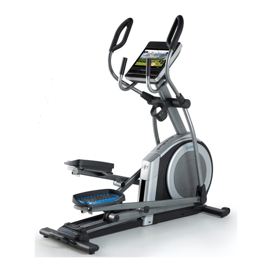
NORDICTRACK COMMERCIAL 14.9 elliptical. The manual. To help us assist you, note the product model COMMERCIAL 14.9 elliptical provides an impressive number and serial number before contacting us. The selection of features designed to make your workouts model number and the location of the serial number at home more effective and enjoyable. -
Page 6: Part Identification Chart
PART IDENTIFICATION CHART Use the drawings below to identify the small parts needed for assembly. The number in parentheses below each drawing is the key number of the part, from the PART LIST near the end of this manual. The number following the key number is the quantity needed for assembly. -
Page 7: Assembly
ASSEMBLY • Assembly requires two persons. one Phillips screwdriver • Place all parts in a cleared area and remove the two adjustable wrenches packing materials. Do not dispose of the packing materials until you fi nish all assembly steps. one rubber mallet •... - Page 8 2. With the help of a second person, place some of the packing materials (not shown) under the rear of the Frame (1). Have the second person hold the Frame to prevent it from tipping while you complete this step. If there are shipping supports attached to the rear of the Frame (1), remove the screws from the shipping supports, and discard the screws...
- Page 9 4. Identify the Right Roller Arm (59), orient it as shown, and slide it onto the right Crank Arm (20). Attach the Right Roller Arm (59) with an M8 x 20mm Screw (95) and a Crank Cover (77). Repeat this step for the Left Roller Arm (45). 5.
- Page 10 6. Tip: Avoid pinching the Main Wire (110). Have a second person hold the Upright (4) on the Avoid pinching the Frame (1). Main Wire (110) Tip: Two M10 x 25mm Screws (92) are preattached to the Frame (1). Attach the Upright (4) with two additional M10 x 25mm Screws (92);...
- Page 11 8. Orient the Right Pedal Arm (58) as shown, and apply grease to the axle. Insert the Right Pedal Arm (58) into the Right Upper Body Leg (60) and into the Right Roller Arm (59). Attach the Right Pedal Arm (58) to the Right Roller Arm (59) with an M8 x 20mm Flat Head Screw (120) and a Retainer (55);...
- Page 12 10. See step 6. Tighten the four M10 x 25mm Screws (92). Next, untie and discard the wire tie on the Main Avoid pinching the wires Wire (110). While a second person holds the Console (7) near the Upright (4), connect the wires on the Console to the Main Wire (110) and to the Extension Wires (111, 146).
- Page 13 12. Orient the Accessory Tray (37) as shown, and attach it to the Upright (4) with two M4 x 16mm Screws (101). 13. Make sure that the Right Control Wire (D) is in the location shown. Orient a Lower Tray Cover (81) as shown, and hold it near the Right Control Wire (D).
- Page 14 14. Identify the Right Upper Body Arm (61), orient it as shown, and hold it near the Right Upper Body Leg (60). Avoid pinching the wires See the left inset drawing. Insert the Right Extension Wire (146) into the Right Upper Body Leg (60) and route it out of the indicated hole (F).
- Page 15 16. Identify the Right Leg Inner Cover (83), orient it as shown, and insert it through the Right Upper Body Leg (60). Next, identify the Right Leg Outer Cover (69), orient it as shown, and press it onto the Right Leg Inner Cover (83).
-
Page 16: How To Plug In The Power Cord
HOW TO PLUG IN THE POWER CORD This product must be earthed. If it should Follow the steps below to plug in the power cord. malfunction or break down, earthing provides a path of least resistance for electric current to reduce the risk 1. -
Page 17: How To Use The Elliptical
HOW TO USE THE ELLIPTICAL HOW TO MOVE THE ELLIPTICAL HOW TO LEVEL THE ELLIPTICAL Due to the size and weight of the elliptical, moving If the elliptical rocks slightly on your floor during use, it requires two persons. Stand in front of the elliptical, turn one or both of the leveling feet (D) beneath hold the upright (A), and place one foot against one the rear stabilizer or turn the leveling foot (E) under... - Page 18 HOW TO EXERCISE ON THE ELLIPTICAL THE OPTIONAL TABLET HOLDER To mount the elliptical, hold the handlebars (G) or the The optional tablet upper body arms (H) and step onto the pedal (I) that is holder (J) will hold in the lower position. Then, step onto the other pedal. your tablet securely Push the pedals until they begin to move with a con- in place and enable...
-
Page 19: How To Use The Console
HOW TO USE THE CONSOLE CONSOLE DIAGRAM FEATURES OF THE CONSOLE When you use the manual mode of the console, you can change the resistance of the pedals and the incline The advanced console offers an array of features of the ramp with the touch of a button. designed to make your workouts more effective and enjoyable. - Page 20 HOW TO TURN ON THE POWER HOW TO USE THE TOUCH SCREEN IMPORTANT: If the elliptical has been exposed to The console features a tablet with a full-color touch cold temperatures, allow it to warm to room tem- screen. The following information will help you use the perature before you turn on the power.
- Page 21 HOW TO SET UP THE CONSOLE 5. Check for firmware updates. Before you use the elliptical for the first time, set up the First, touch the menu button (three horizontal lines console. symbol), touch Settings, touch Maintenance, and then touch Update. The console will check for firm- 1.
- Page 22 HOW TO USE THE MANUAL MODE Note: After you press a button, it will take a moment for the pedals to reach the selected resis- 1. Touch the screen or press any button on the tance level or for the ramp to reach the selected console to turn on the console.
- Page 23 5. Wear a compatible heart rate monitor and 6. Turn on the fan if desired. measure your heart rate if desired. The fan has several speed You can wear a compatible heart rate monitor to settings, including an auto measure your heart rate. Note: The console is mode.
- Page 24 HOW TO USE A FEATURED WORKOUT OR AN To draw your own map for a workout, see HOW TO ONBOARD WORKOUT CREATE A DRAW-YOUR-OWN-MAP WORKOUT on page 26. 1. Touch the screen or press any button on the console to turn on the console. When you select a workout, the screen will show an overview of the workout that includes details See HOW TO TURN ON THE POWER on...
- Page 25 If the resistance level and/or incline level is too high When the workout ends, a workout summary will or too low, you can manually override the setting appear on the screen. If desired, you can select by pressing the Resistance buttons or the Ramp options such as adding the workout to your sched- buttons.
- Page 26 HOW TO CREATE A DRAW-YOUR-OWN-MAP If you make a mistake, touch Undo in the map WORKOUT options. 1. Touch the screen or press any button on the The screen will display the elevation and distance console to turn on the console. statistics for your workout.
- Page 27 HOW TO USE AN IFIT WORKOUT 4. Select an iFit workout from the home screen or the workout library. To use an iFit workout, you must be logged into your iFit account (see step 3 below) and the console Touch the buttons at the bottom of the screen to must be connected to a wireless network (see HOW select either the home screen (Home button) or the TO CONNECT TO A WIRELESS NETWORK on...
- Page 28 6. Create a list of favorite iFit workouts if desired. 9. Wear a compatible heart rate monitor and measure your heart rate if desired. To mark an iFit workout as a favorite, simply view the overview or workout summary of the desired See step 5 on page 23.
- Page 29 HOW TO CHANGE CONSOLE SETTINGS 3. Customize the unit of measurement and other settings. IMPORTANT: Some of the settings and features described may not be enabled. Occasionally, a To customize the unit of measurement, the time firmware update may cause your console to function zone, or other settings, touch Equipment Info or slightly differently.
- Page 30 6. Calibrate the incline system. 3. Enable Wi-Fi. To calibrate the incline system, touch Maintenance, Make sure that Wi-Fi ® is enabled. If it is not touch Calibrate Incline, and then touch Begin. The enabled, touch the Wi-Fi toggle to enable it. ramp will automatically rise to the maximum incline level, lower to the minimum incline level, and then 4.
- Page 31 HOW TO USE THE SOUND SYSTEM Connect Your Headphones If the console has a headphones jack, you can plug Connect with an Audio Cable your headphones into the headphones jack to listen to To play music or audio books through the console audio from the console through your headphones.
-
Page 32: Maintenance And Troubleshooting
MAINTENANCE AND TROUBLESHOOTING MAINTENANCE If the console does not boot up properly, or if the con- Regular maintenance is important for optimal sole freezes and does not performance and to reduce wear. Inspect and respond, reset the console properly tighten all parts each time the elliptical is to the factory default set- used. - Page 33 HOW TO ADJUST THE REED SWITCH HOW TO ADJUST THE DRIVE BELT If the console does not display correct feedback, If the pedals slip while you are pedaling, even while the reed switch should be adjusted. To adjust the the resistance is adjusted to the highest level, the drive reed switch, first press the power switch to the off belt may need to be adjusted.
-
Page 34: Exercise Guidelines
EXERCISE GUIDELINES Aerobic Exercise—If your goal is to strengthen your WARNING: cardiovascular system, you must perform aerobic Before beginning this exercise, which is activity that requires large amounts or any exercise program, consult your physi- of oxygen for prolonged periods of time. For aerobic cian. -
Page 35: Part List
PART LIST Model No. NTEL71420-INT.0 R0421A Key No. Qty. Description Key No. Qty. Description Frame/Ramp Roller Rear Stabilizer Left Pedal Handle Access Cover Axle Cover Upright Pivot Spacer M4 x 19mm Screw Retainer Front Stabilizer Roller Arm Bushing Console Pedal Arm Bearing Roller Guide Right Pedal Arm Crank Bearing Sleeve... - Page 36 Key No. Qty. Description Key No. Qty. Description M4 x 16mm Screw M4 x 25mm Screw M8 Locknut Disc Bracket M6 x 12mm Screw Long Bumper M10 x 115mm Screw M8 x 22mm Washer M4 x 25mm Flange Screw M4 x 12mm Screw Lower Ramp Cover Adhesive Tape Crank Spacer...
-
Page 37: Exploded Drawing
EXPLODED DRAWING A Model No. NTEL71420-INT.0 R0421A... - Page 38 EXPLODED DRAWING B Model No. NTEL71420-INT.0 R0421A...
- Page 39 EXPLODED DRAWING C Model No. NTEL71420-INT.0 R0421A...
-
Page 40: Ordering Replacement Parts
ORDERING REPLACEMENT PARTS To order replacement parts, please see the front cover of this manual. To help us assist you, be prepared to provide the following information when contacting us: • the model number and serial number of the product (see the front cover of this manual) •...
Need help?
Do you have a question about the Commercial 14.9 and is the answer not in the manual?
Questions and answers