Table of Contents
Advertisement
Quick Links
1
SET CLOCK, YEAR, MONTH, DAY
1. Press ▲/ ▼ to select 12 or 24 HR mode, then
press
Next.
2. Press ▲/ ▼to select hour, then press Next.
3. Press ▲/▼to select minutes, then press Next.
4. Press ▲/ ▼ to select current year, then press Next.
5. Press ▲/ ▼ to select current month, press Next.
6. Press ▲/ ▼ to select the calendar day number.
7. Press
to complete operation.
Done
Note: Select
More >
2
ACCESS SERVICE MENUS
1. Hold lower right and lower left keys for fi ve
seconds.
2. Press
or
Next
Go Back
Service Menu.
3. Press ▲/ ▼ to select option.
4. Press
when complete.
Done
© COPYRIGHT 2013 PECO, INC. ALL RIGHTS RESERVED.
Clock, to access after setup.
button to select a
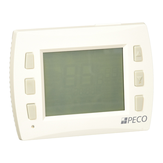
PERFORMANCE PRO MULTI-FAN
3
CONFIGURE SERVICE MENUS
The following Service Menus (SM) commonly require
confi guration. Please verify that these are set for your
specifi c application. Additional confi guration may be
required. Refer to Table 2 for all available Service Menus.
• SM 100 = Programmable or Nonprogrammable
• SM 110 = System Type
• SM 121 = Number of Fan Speeds
• SM 130 = Reversing Valve
• SM 135 = W1 heat output NO or NC
• SM 170 = Remote Sensors
• SM 265 = Single or Dual Setpoint Operation
4
WIRING: TERMINAL DESIGNATIONS
1. Connect wires for appropriate system type
(Table 1).
▲
!
WARNING: DISCONNECT POWER BEFORE BEGINNING INSTALLATION.
• CAUTION: Use copper wire only. Insulate or wire-nut all unused leads.
• Use care to avoid electrostatic discharge to thermostat
• CAUTION: Do not connect unused wires together
• ALL ELECTRICAL LOADS MUST BE CONNECTED TO TERMINAL C
(24 VAC).
TABLE 1. TERMINAL BLOCK DESIGNATIONS
Fan Coil (Conventional)
C
24 VAC, Unswitched side
Service
W1
Stage 1 Heat
Menu
Current
W2
Stage 2 Heat
option
G
FAN High
A
FAN Medium
E
FAN Low
Y1
Stage 1 Cool
Y2
Stage 2 Cool
24 VAC Power for heating,
RH
switched side
24 VAC Power for cooling,
RC
switched side
SC
Sensor Common
S1
Indoor Remote Sensor
S2
Occupancy Sensor
Seasonal Changeover Switch
S3
OPEN=Cooling in Summer
CLOSED=Heating in Winter
QUICK START GUIDE
Heat Pump
C
24 VAC, Unswitched side
B/O
Reversing Valve
AUX
Auxiliary Heat (Stage 2 or 3)
G
FAN High
A
FAN Medium
E
FAN Low
Y1
Compressor Stage 1
Y2
Compressor Stage 2
24 VAC Power for heating,
RH
switched side
24 VAC Power for cooling,
RC
switched side
SC
Sensor Common
S1
Indoor Remote Sensor
S2
Occupancy Sensor
S3
NA
P/N 70864 3220-2318 REV 00
Advertisement
Table of Contents

Related Manuals for Peco PERFORMANCE PRO MULTI-FAN


Summary of Contents for Peco PERFORMANCE PRO MULTI-FAN
-
Page 1: Quick Start Guide
4. Press when complete. Done Sensor Common Sensor Common Indoor Remote Sensor Indoor Remote Sensor Occupancy Sensor Occupancy Sensor Seasonal Changeover Switch OPEN=Cooling in Summer CLOSED=Heating in Winter © COPYRIGHT 2013 PECO, INC. ALL RIGHTS RESERVED. P/N 70864 3220-2318 REV 00... - Page 2 10 = 2 Heat/ 2 Cool heat pump (no auxiliary heat) 11= 3 Heat/ 2 Cool heat pump (with auxiliary heat) and Emergency (Em) heat 12 = NA 13= NA © COPYRIGHT 2013 PECO, INC. ALL RIGHTS RESERVED. P/N 70864 3220-2318 REV 00...
- Page 3 Backlight Backlight temporarily on Backlight always on (low intensity, 24V only) Remote Sensor Select sensor if used. Contact PECO for information on the T8000 Series Indoor Remote Zone Sensor. No Remote Sensors Remote Indoor Sensor Only Not Used Not Used...
- Page 4 System Fan Test Disabled Output Low Speed Medium Speed High Speed Factory Use Only Factory Use Only Factory Use Only Factory Use Only Factory Use Only Factory Use Only © COPYRIGHT 2013 PECO, INC. ALL RIGHTS RESERVED. P/N 70864 3220-2318 REV 00...
Need help?
Do you have a question about the PERFORMANCE PRO MULTI-FAN and is the answer not in the manual?
Questions and answers