ASROCK X58 Extreme User Manual
Hide thumbs
Also See for X58 Extreme:
- Installation manual (216 pages) ,
- Brochure (3 pages) ,
- User manual (74 pages)

Related Manuals for ASROCK X58 Extreme


Summary of Contents for ASROCK X58 Extreme
-
Page 1: User Manual
X58 Extreme User Manual Version 1.1 Published July 2009 Copyright©2009 ASRock INC. All rights reserved. 1 1 1 1 1... - Page 2 (including damages for loss of profits, loss of business, loss of data, interruption of business and the like), even if ASRock has been advised of the possibility of such damages arising from any defect or error in the manual or product.
-
Page 3: Table Of Contents
Contents Contents Contents Contents Contents 1 Introduction 1 Introduction ...................... 5 5 5 5 5 ........... 1 Introduction 1 Introduction ........... 1 Introduction ........... 1.1 Package Contents ............5 1.2 Specifications ..............6 1.3 Two SLI Graphics Card Support List ......10 1.4 Two CrossFireX Graphics Card Support List .... - Page 4 2.20.4 Installing Windows ® Vista / Vista 64-bit With RAID Functions ........... 50 ® 2.21 Installing Windows XP / XP 64-bit / Vista / Vista 64-bit Without RAID Functions ..........51 2.21.1 Installing Windows ® XP / XP 64-bit Without RAID Functions ............
-
Page 5: Introduction
In case any modifications of this manual occur, the updated version will be available on ASRock website without further notice. You may find the latest VGA cards and CPU support lists on ASRock website as well. ASRock website http://www.asrock.com If you require technical support related to this motherboard, please visit our website for specific information about the model you are using. -
Page 6: Specifications
Specifications Specifications Specifications Specifications Specifications Platform - ATX Form Factor: 12.0-in x 9.6-in, 30.5 cm x 24.4 cm - All Solid Capacitor design (100% Japan-made high-quality Conductive Polymer Capacitors) ® - Intel Socket 1366 Core i7 Processor Extreme Edition / Core i7 Processor Supports Intel ®... - Page 7 - Supports Smart BIOS Support CD - Drivers, Utilities, AntiVirus Software (Trial Version) Unique Feature - ASRock OC Tuner (see CAUTION 8) - Intelligent Energy Saver (see CAUTION 9) - Instant Boot - ASRock Instant Flash (see CAUTION 10) 7 7 7 7 7...
- Page 8 Certifications - FCC, CE, WHQL * For detailed product information, please visit our website: http://www.asrock.com WARNING Please realize that there is a certain risk involved with overclocking, including adjusting the setting in the BIOS, applying Untied Overclocking Technology, or using the third- party overclocking tools.
- Page 9 Please visit our website for the operation pro- cedures of Intelligent Energy Saver. ASRock website: http://www.asrock.com 10. ASRock Instant Flash is a BIOS flash utility embedded in Flash ROM. This convenient BIOS update tool allows you to update system BIOS ®...
-
Page 10: Tm Graphics Card Support List
LEADTEK PX9800GTX GeForce 9800GTX 182.50 LEADTEK PX9800 GTX+ GeForce 9800GTX+ 182.50 GIGABYTE GV-N26-896H-B GeForce GTX260 182.50 * For the latest updates of the supported PCI Express VGA card list for SLI Mode, please visit our website for details. ASRock website: http://www.asrock.com/support/index.htm... -
Page 11: Tm Graphics Card Support List
Gecube GC-HD485PG3-E3 RADEON 4850 Catalyst 9.1 * For the latest updates of the supported PCI Express VGA card list for CrossFireX Mode, please visit our website for details. ASRock website: http://www.asrock.com/support/index.htm Three CrossFireX Three CrossFireX Three CrossFireX Three CrossFireX Three CrossFireX... -
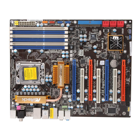
Page 12: Motherboard Layout
Top: T: USB6 RJ-45 B: USB7 Intel NB_FAN1 Chipset PCIE1 PCI Express 2.0 AUDIO PCIE2 CODEC PCIE3 RoHS 1394a VT6330 PCI1 X58 Extreme BIOS PCIE4 Intel CMOS PCI2 Battery ICH10R PCIE5 FLOPPY1 USB10_11 COM1 Debug CHA_FAN1 HDMI_SPDIF1 CLRCMOS1 RSTBTN PWRBTN... -
Page 13: I/O Panel
I/O Panel I/O Panel I/O Panel I/O Panel I/O Panel PS/2 Mouse Port (Green) ** 10 Front Speaker (Lime) Coaxial SPDIF Out Port Microphone (Pink) USB 2.0 Port (USB0) USB 2.0 Ports (USB67) IEEE 1394 Port (IEEE 1394) USB 2.0 Ports (USB45) LAN RJ-45 Port USB 2.0 Ports (USB23) Side Speaker (Gray) -
Page 14: Installation
Chapter 2: Installation Chapter 2: Installation Chapter 2: Installation Chapter 2: Installation Chapter 2: Installation This is an ATX form factor (12.0" x 9.6", 30.5 x 24.4 cm) motherboard. Before you install the motherboard, study the configuration of your chassis to ensure that the motherboard fits into it. -
Page 15: Cpu Installation
2.3 CPU Installation 2.3 CPU Installation 2.3 CPU Installation 2.3 CPU Installation 2.3 CPU Installation For the installation of Intel 1366-Pin CPU, Load Plate please follow the steps below. Socket Body Contact Array Load Lever 1366-Pin Socket Overview Before you insert the 1366-Pin CPU into the socket, please check if the CPU surface is unclean or if there is any bent pin on the socket. - Page 16 Step 3. Insert the 1366-Pin CPU: Step 3-1. Hold the CPU by the edges where are marked with black lines. Step 3-2. Orient the CPU with IHS (Integrated Heat Sink) up. Locate Pin1 and the two ori- entation key notches. orientation key notch alignment key Pin1...
-
Page 17: Installation Of Heatsink And Cpu Fan
Installation of CPU Fan and Heatsink Installation of CPU Fan and Heatsink Installation of CPU Fan and Heatsink Installation of CPU Fan and Heatsink Installation of CPU Fan and Heatsink This motherboard is equipped with 1366-Pin socket that supports Intel 1366-Pin CPU. Please adopt the type of heatsink and cooling fan compliant with Intel 1366-Pin CPU to dissipate heat. -
Page 18: Installation Of Memory Modules (Dimm)
2.5 Installation of Memor 2.5 Installation of Memor 2.5 Installation of Memor y Modules (DIMM) 2.5 Installation of Memor 2.5 Installation of Memor y Modules (DIMM) y Modules (DIMM) y Modules (DIMM) y Modules (DIMM) This motherboard provides six 240-pin DDR3 (Double Data Rate 3) DIMM slots, and supports Triple Channel Memory Technology. - Page 19 Installing a DIMM Installing a DIMM Installing a DIMM Installing a DIMM Installing a DIMM Please make sure to disconnect power supply before adding or removing DIMMs or the system components. Step 1. Unlock a DIMM slot by pressing the retaining clips outward. Step 2.
-
Page 20: Expansion Slots (Pci And Pci Express Slots)
2.6 Expansion Slots (PCI and PCI Express Slots) 2.6 Expansion Slots (PCI and PCI Express Slots) 2.6 Expansion Slots (PCI and PCI Express Slots) 2.6 Expansion Slots (PCI and PCI Express Slots) 2.6 Expansion Slots (PCI and PCI Express Slots) There are 2 PCI slots and 5 PCI Express slots on this motherboard. -
Page 21: Sli Tm And Quad Sli Tm Operation Guide
2.7 SLI 2.7 SLI 2.7 SLI 2.7 SLI 2.7 SLI and Quad SLI and Quad SLI and Quad SLI and Quad SLI and Quad SLI Operation Guide Operation Guide Operation Guide Operation Guide Operation Guide This motherboard supports NVIDIA ® and Quad SLI (Scalable Link Interface) technology that allows you to install up to two identical PCI Express x16 graphics... - Page 22 Step3. Align and insert ASRock SLI_Bridge_2S Card to the goldfingers on each graphics card. Make sure ASRock SLI_Bridge_2S Card is firmly in place. ASRock SLI_Bridge_2S Card Step4. Connect a VGA cable or a DVI cable to the monitor connector or the DVI...
- Page 23 2.7.2 Driver Installation and Setup 2.7.2 Driver Installation and Setup 2.7.2 Driver Installation and Setup 2.7.2 Driver Installation and Setup 2.7.2 Driver Installation and Setup Install the graphics card drivers to your system. After that, you can enable the Multi- ®...
- Page 24 For Windows ® Vista / Vista 64-bit OS: (For SLI and Quad SLI mode) A. Click the Start icon on your Windows taskbar. B. From the pop-up menu, select All Programs, and then click NVIDIA Corporation. C. Select NVIDIA Control Panel tab. D.
-
Page 25: Crossfirex
CrossF CrossF CrossFireX CrossF CrossF ireX ireX ireX ireX , 3- , 3- , 3- , 3- , 3-W W W W W ay CrossF ay CrossF ay CrossF ay CrossF ay CrossFireX ireX ireX ireX ireX and Quad and Quad and Quad and Quad and Quad... - Page 26 Step 2. Connect two Radeon graphics cards by installing CrossFire Bridge on CrossFire Bridge Interconnects on the top of Radeon graphics cards. (CrossFire Bridge is provided with the graphics card you purchase, not bundled with this motherboard. Please refer to your graphics card vendor for details.) CrossFire Bridge Step 3.
- Page 27 2.8.1.2 Installing Three CrossFireX 2.8.1.2 Installing Three CrossFireX 2.8.1.2 Installing Three CrossFireX 2.8.1.2 Installing Three CrossFireX 2.8.1.2 Installing Three CrossFireX -Ready Graphics -Ready Graphics -Ready Graphics -Ready Graphics -Ready Graphics Cards Cards Cards Cards Cards Step 1. Insert Radeon graphics cards into PCIE2, PCIE4 and PCIE5 slots. Make sure that the cards are properly seated on the slots.
- Page 28 2.8.2 Driver Installation and Setup 2.8.2 Driver Installation and Setup 2.8.2 Driver Installation and Setup 2.8.2 Driver Installation and Setup 2.8.2 Driver Installation and Setup Step 1. Power on your computer and boot into OS. Step 2. Remove the ATI driver if you have any VGA driver installed in your system.
- Page 29 Although you have selected the option “Enable CrossFire ”, the CrossFireX function may not work actually. Your computer will automatically reboot. After restarting your computer, please confirm whether the option “Enable CrossFire ” in “ATI Catalyst Control Center” is selected or not; if not, please select it again, and then you are able to enjoy the benefit of CrossFireX feature.
-
Page 30: Surround Display Feature
2.9 Surround Display Feature 2.9 Surround Display Feature 2.9 Surround Display Feature 2.9 Surround Display Feature 2.9 Surround Display Feature This motherboard supports Surround Display upgrade. With the external add-on PCI Express VGA cards, you can easily enjoy the benefits of Surround Display feature. -
Page 31: Onboard Headers And Connectors
2.11 Onboard Headers and Connectors 2.11 Onboard Headers and Connectors 2.11 Onboard Headers and Connectors 2.11 Onboard Headers and Connectors 2.11 Onboard Headers and Connectors Onboard headers and connectors are NOT jumpers. Do NOT place jumper caps over these headers and connectors. Placing jumper caps over the headers and connectors will cause permanent damage of the motherboard! FDD connector... - Page 32 Serial ATA (SATA) Please connect the black end of Power Cable SATA power cable to the power connector on each drive. Then (Optional) connect to the SATA HDD connect the white end of SATA power connector power cable to the power connect to the connector of the power supply.
- Page 33 Front Panel Audio Header This is an interface for front PRESENCE# panel audio cable that allows (9-pin HD_AUDIO1) MIC_RET OUT_RET convenient connection and (see p.12 No. 41) control of audio devices. OUT2_L J_SENSE OUT2_R MIC2_R MIC2_L 1. High Definition Audio supports Jack Sensing, but the panel wire on the chassis must support HDA to function correctly.
- Page 34 PLED+ System Panel Header This header accommodates PLED- PWRBTN# several system front panel (9-pin PANEL1) functions. (see p.12 No. 9) DUMMY RESET# HDLED- HDLED+ Chassis Speaker Header Please connect the chassis SPEAKER speaker to this header. (4-pin SPEAKER 1) DUMMY DUMMY (see p.12 No.
- Page 35 Though this motherboard provides 24-pin ATX power connector, it can still work if you adopt a traditional 20-pin ATX power supply. To use the 20-pin ATX power supply, please plug your power supply along with Pin 1 and Pin 13. 20-Pin ATX Power Supply Installation ATX 12V Power Connector Please connect an ATX 12V...
- Page 36 HDMI_SPDIF Cable Please connect the black end (A) of HDMI_SPDIF cable to the (Optional) HDMI_SPDIF header on the motherboard. Then connect the white end (B or C) of HDMI_SPDIF cable to the HDMI_SPDIF connector of HDMI VGA card. A. black end B.
-
Page 37: Quick Switches
2.12 Quick Switches 2.12 Quick Switches 2.12 Quick Switches 2.12 Quick Switches 2.12 Quick Switches This motherboard has three quick switches: power switch, reset switch and clear CMOS switch, allowing users to quickly turn on/off or reset the system or clear the CMOS values. -
Page 38: Debug Led
2.13 Debug LED 2.13 Debug LED 2.13 Debug LED 2.13 Debug LED 2.13 Debug LED The onboard Debug LED is used to provide code information, which makes troubleshooting even easier. Please see the diagrams below for reading the Debug LED codes. The Bootblock initialization code sets up the chipset, memory and other components before system memory is available. - Page 39 The POST code checkpoints are the largest set of checkpoints during the BIOS pre-boot process. The following table describes the type of checkpoints that may occur during the POST portion of the BIOS: Checkpoint Description Disable NMI, Parity, video for EGA, and DMA controllers. Initialize BIOS, POST, Runtime data area.
- Page 40 Initializes the silent boot module. Set the window for displaying text information. Displaying sign-on message, CPU information, setup key message, and any OEM specific information. Initializes different devices through DIM. Initializes DMAC-1 & DMAC-2. Initialize RTC date/time. Test for total memory installed in the system. Also, Check for DEL or ESC keys to limit memory test.
-
Page 41: Hdmi_Spdif Header Connection Guide
2.14 HDMI_SPDIF Header Connection Guide 2.14 HDMI_SPDIF Header Connection Guide 2.14 HDMI_SPDIF Header Connection Guide 2.14 HDMI_SPDIF Header Connection Guide 2.14 HDMI_SPDIF Header Connection Guide HDMI (High-Definition Multi-media Interface) is an all-digital audio/video specification, which provides an interface between any compatible digital audio/ video source, such as a set-top box, DVD player, A/V receiver and a compatible digital audio or video monitor, such as a digital television (DTV). -
Page 42: Sataii Hard Disk Setup Guide
2.15 SA 2.15 SA 2.15 SAT T T T T AII Hard Disk Setup Guide 2.15 SA 2.15 SA AII Hard Disk Setup Guide AII Hard Disk Setup Guide AII Hard Disk Setup Guide AII Hard Disk Setup Guide Before installing SATAII hard disk to your computer, please carefully read below SATAII hard disk setup guide. -
Page 43: Installation
2.16 2.16 2.16 2.16 2.16 Serial A Serial A Serial A Serial AT T T T T A (SA Serial A A (SA A (SA A (SAT T T T T A) / Serial A A (SA A) / Serial A A) / Serial A A) / Serial A A) / Serial AT T T T T AII (SA... -
Page 44: Hdds
2.17 Hot Plug and Hot Swap F 2.17 Hot Plug and Hot Swap F 2.17 Hot Plug and Hot Swap Functions for SA 2.17 Hot Plug and Hot Swap F 2.17 Hot Plug and Hot Swap F unctions for SA unctions for SA unctions for SAT T T T T A / SA unctions for SA... -
Page 45: Guide
SATA / SATAII Hot Plug support information of our motherboard is indicated in the product spec on our website: www.asrock.com 2. Make sure your SATA / SATAII HDD can support Hot Plug function from your dealer or HDD user manual. - Page 46 How to Hot Plug a SATA / SATAII HDD: Points of attention, before you process the Hot Plug: Please do follow below instruction sequence to process the Hot Plug, improper procedure will cause the SATA / SATAII HDD damage and data loss. Step 1 Step 2 Please connect SATA power cable 1x4-pin end...
-
Page 47: Driver Installation Guide
2.19 2.19 2.19 2.19 2.19 Driver Installation Guide Driver Installation Guide Driver Installation Guide Driver Installation Guide Driver Installation Guide To install the drivers to your system, please insert the support CD to your optical drive first. Then, the drivers compatible to your system can be auto-detected and listed on the support CD driver page. -
Page 48: Setting Up A "Raid Ready" System
STEP 3: Use “RAID Installation Guide” to set RAID configuration. Before you start to configure the RAID function, you need to check the installation guide in the Support CD for proper configuration. Please refer to the document in the Support CD, “Guide to SATA Hard Disks Installation and RAID Configuration”, which is located in the folder at the following path: .. -
Page 49: Migrating A "Raid Ready" System To Raid
install. You may select: "Intel(R) ICH10R SATA RAID Controller (Desktop - ® Windows XP)" for Windows XP or "Intel(R) ICH10R SATA RAID Controller ® (Desktop - Windows XP64)" for Windows XP 64-bit. 5. Finish the Windows ® installation and install all necessary drivers. 6. -
Page 50: Installing Windows
/ Vista 64-bit OS on your system. When you see “Where do you want to install Windows?” page, please insert the ASRock Support CD into your optical drive, and click the “Load ® ® Driver” button on the left on the bottom to load the Intel RAID drivers. -
Page 51: Installing Windows ® Xp / Xp 64-Bit / Vista
2.21 2.21 2.21 2.21 2.21 Installing Windows Installing Windows Installing Windows Installing Windows Installing Windows ® XP / XP 64-bit / Vista XP / XP 64-bit / Vista XP / XP 64-bit / Vista XP / XP 64-bit / Vista XP / XP 64-bit / Vista / Vista / Vista... -
Page 52: Installing Windows
/ Vista 64-bit OS on your system. When you see “Where do you want to install Windows?” page, please insert the ASRock Support CD into your optical drive, and click the “Load Driver” button ® ® on the left on the bottom to load the Intel AHCI drivers. -
Page 53: Bios Setup Utility
Chapter 3: BIOS SETUP UTILITY Chapter 3: BIOS SETUP UTILITY Chapter 3: BIOS SETUP UTILITY Chapter 3: BIOS SETUP UTILITY Chapter 3: BIOS SETUP UTILITY 3 . 1 3 . 1 Introduction Introduction 3 . 1 3 . 1 3 . 1 Introduction Introduction Introduction... -
Page 54: Navigation Keys
System Time [ :00:09] or [SHIFT-TAB] to System Date [Mon 07/20/2009] select a field. BIOS Version : X58 Extreme P1.00 Use [+] or [-] to Processor Type : Intel (R) CPU configure system Time. 000 @ 3.20GHz (64bit) Processor Speed... - Page 55 3.3 OC T OC T OC T OC T OC Tweak weak weak weak weaker Screen er Screen er Screen er Screen er Screen In the OC Tweaker screen, you can set up overclocking features. BIOS SETUP UTILITY Main OC Tweaker Advanced H/W Monitor Boot...
- Page 56 CPU Ratio If the ratio status is unlocked, you will find this item appear to allow you changing the ratio value of this motherboard. QPI Frequency Use this option to adjust QPI (QuickPath Interconnect) frequency. Configu- ration options: [Auto], [4.800GT], [5.866GT] and [6.400GT]. The default value is [Auto].
- Page 57 Use this item to adjust DRAM Command Rate. Configuration options : [1], [2] and [Auto]. ASRock VDrop Control Use this to enable or disable ASRock VDrop control. Configuration options: [With VDrop] and [Without VDrop]. The default value is [With VDrop]. CPU Voltage Use this to select CPU Voltage.
- Page 58 ICH Voltage Use this to select ICH Voltage. Standard: 1.12V. Max: 1.56V. Increment: 0.02V. IOH CSI Voltage Use this to select IOH CSI Voltage. Standard: 1.12V. Max: 1.56V. Increment: 0.02V. IOH/ICH PCIE Voltage Use this to select IOH/ICH PCIE Voltage. Standard: 1.52V. Max: 1.90V. Increment: 0.02V.
-
Page 59: Advanced Screen
Setting wrong values in this section may cause the system to malfunction. ASRock Instant Flash ASRock Instant Flash is a BIOS flash utility embedded in Flash ROM. This convenient BIOS update tool allows you to update system BIOS without ®... -
Page 60: Cpu Configuration
3 . 4 . 1 3 . 4 . 1 3 . 4 . 1 CPU Configuration 3 . 4 . 1 3 . 4 . 1 CPU Configuration CPU Configuration CPU Configuration CPU Configuration BIOS SETUP UTILITY Advanced Configure advanced CPU settings Select the ration between CPU Core Intel (R) Core (TM) i7 CPU... - Page 61 Hyper Threading Technology To enable this feature, it requires a computer system with an Intel Core processor that supports Hyper-Threading technology and an operating system ® ® that includes optimization for this technology, such as Microsoft Windows XP or Vista .
- Page 62 TDP Limit value Program the TDP (power) limit for Turbo Mode so that the processor does not throttle at peak performance conditions. Intel (R) C-STATE tech. Intel (R) C-STATE tech. is achieved by making the power and thermal control unit part of the core logic and not part of the chipset as before. Migration of the power and thermal management flow into the processor allows us to use a hardware coordination mechanism in which each core can request any C-state it wishes, thus allowing for individual core savings to be maximized.
-
Page 63: Chipset Configuration
3 . 4 . 2 3 . 4 . 2 3 . 4 . 2 Chipset Configuration 3 . 4 . 2 3 . 4 . 2 Chipset Configuration Chipset Configuration Chipset Configuration Chipset Configuration BIOS SETUP UTILITY Advanced Chipset Settings [PCI] Primary Graphics Adapter Onboard HD Audio... -
Page 64: Acpi Configuration
3.4.3 3.4.3 3.4.3 ACPI Configuration 3.4.3 3.4.3 ACPI Configuration ACPI Configuration ACPI Configuration ACPI Configuration BIOS SETUP UTILITY Advanced ACPI Configuration Select auto-detect or disable the STR feature. [Auto] Suspend To RAM [No] Repost Video on STR Resume [Enabled] Check Ready Bit [Power Off] Restore on AC/Power Loss [Disabled]... -
Page 65: Ide Configuration
ACPI HPET Table Use this item to enable or disable ACPI HPET Table. The default value is [Disabled]. Please set this option to [Enabled] if you plan to use this ® motherboard to submit Windows Vista certification. 3 . 4 . 4 3 . - Page 66 IDE Device Configuration You may set the IDE configuration for the device that you specify. We will use the “Primary IDE Master” as the example in the following instruction. BIOS SETUP UTILITY Advanced Primary IDE Master Select the type of device connected Device :Hard Disk to the system.
-
Page 67: Pcipnp Configuration
DMA Mode DMA capability allows the improved transfer-speed and data-integrity for com- patible IDE devices. S.M.A.R.T. Use this item to enable or disable the S.M.A.R.T. (Self-Monitoring, Analysis, and Reporting Technology) feature. Configuration options: [Disabled], [Auto], [Enabled]. 32-Bit Data Transfer Use this item to enable 32-bit access to maximize the IDE hard disk data transfer rate. -
Page 68: Floppy Configuration
3 . 4 . 6 3 . 4 . 6 3 . 4 . 6 Floppy Configuration 3 . 4 . 6 3 . 4 . 6 Floppy Configuration Floppy Configuration Floppy Configuration Floppy Configuration In this section, you may configure the type of your floppy drive. BIOS SETUP UTILITY Advanced Floppy Configuration... -
Page 69: Usb Configuration
3 . 4 . 8 3 . 4 . 8 3 . 4 . 8 USB Configuration 3 . 4 . 8 3 . 4 . 8 USB Configuration USB Configuration USB Configuration USB Configuration BIOS SETUP UTILITY Advanced USB Configuration To enable or disable the onboard USB controllers. -
Page 70: Hardware Health Event Monitoring Screen
3 . 5 3 . 5 3 . 5 Hardware Health Event Monitoring Screen 3 . 5 3 . 5 Hardware Health Event Monitoring Screen Hardware Health Event Monitoring Screen Hardware Health Event Monitoring Screen Hardware Health Event Monitoring Screen In this section, it allows you to monitor the status of the hardware on your system, including the parameters of the CPU temperature, motherboard temperature, CPU fan speed, chassis fan speed, and the critical voltage. -
Page 71: Boot Screen
3 . 6 3 . 6 3 . 6 3 . 6 3 . 6 Boot Screen Boot Screen Boot Screen Boot Screen Boot Screen In this section, it will display the available devices on your system for you to configure the boot settings and the boot priority. -
Page 72: Security Screen
Use this option to select logo in POST screen. This option only appears when you enable the option “Full Screen Logo”. Configuration options: [Auto], [PCIE2.0 Revolution], [Scenery] and [ASRock]. The default value is [Auto]. Currently, the option [Auto] is set to Aircraft. -
Page 73: Exit Screen
3.8 Exit Screen Exit Screen Exit Screen Exit Screen Exit Screen BIOS SETUP UTILITY Main OC Tweaker Advanced H/W Monitor Boot Security Exit Exit Options Exit system setup after saving the Save Changes and Exit changes. Discard Changes and Exit Discard Changes F10 key can be used for this operation. -
Page 74: Install Operating System
C o n t a c t I n f o r m a t i o n If you need to contact ASRock or want to know more about ASRock, welcome to visit ASRock’s website at http://www.asrock.com; or you may contact your...
Need help?
Do you have a question about the X58 Extreme and is the answer not in the manual?
Questions and answers